


Euphonix System 5 Installation Guide
Interconnecting System Components
34
NOTE:
It is the responsibility of the system designers, system integrators, and end
users to assure that the choice of cabling, terminations, equalizations, etc. con-
form to the recommended practice. Although maximum recommended distan-
ces over copper can be exceeded with the use of high performance compo-
nents (including cables), it is not Euphonix's intention to endorse any particular
brand or method of achieving the end result.
MADI Hookup
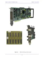
Figure 2-14:
M ADI hoo kup: primary DF66 SuperCore, CO660 Changeover Switch, backup DF66 SuperCore
To/From MADI
Converters*
DF66 - 1
(Main DSP)
DF66 - 1A
(Backup DSP)
CO600
DSP A
MADI
I/O
DSP B
MADI
I/O
System
MADI
I/O
MADI
I/O
MADI
I/O
1
2
3
4
1
2
3
4
1
2
3
4
1
2
3
4
1 2 3 4
- Each Green interconnect line represents four (4) MADI
connections.
- A single CO600 can hold four (4) CO601 Changeover cards.
- Each CO601 is capable of handling 4 In, 4 Out MADI
connections from and to input/output converters. It
distributes/switches these inputs/outputs to and from each
DF66 DSP core.
- Interconnections between CO600 and DF66 are made using
Euphonix-supplied cabling.
- Input and output from the CO600 is provided by Euphonix-
supplied cabling, terminating to BNC "Bulkhead" panels.
- Above Configuration shows a total of 16 MADI connections in
and out of the CO600/DSP
*) Output Port 1, MADI connection #1 is reserved for the
MA703/MC524 monitoring output


