11
2123622-04-06/19 (translation of the original operating instructions)
Operating Instructions Safety Systems
MGB-L..B-PN.-… (PROFINET) and With Expanded Data Structure Type C
EN
7.2.
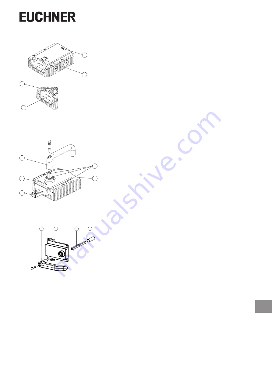
Evaluation module MGB-L.-
2
1
3
4
Key
:
1
LED indicator
2
Cover for mechanical release
3
Locking arm (only for version with guard locking)
4
Auxiliary marking for max. permitted mounting distance
Notice
:
Depending on the version, additional controls and indicators may be integrated into
the cover. See enclosed data sheet.
Figure 3:
Evaluation module MGB-L.-
7.3.
Handle module MGB-H-…
1
2
3
3
4
Key
:
1
Door handle
2
Locking screws T10 for housing cover and handle adjustment
3
Fold-out locking mechanism
(optional: second, automatically extending lockout mechanism)
4
Bolt tongue
Notice
:
Depending on the version, a mounting plate can be included.
See enclosed data sheet.
Figure 4:
Handle module MGB-H-…
7.4.
Escape release MGB-E-... (optional)
1
2
3
4
Key
:
1
Door handle
2
Housing
3
Actuation axis 8 x 8 mm
(different lengths available)
4
Protective sleeve
Notice
:
Depending on the version, a mounting plate can be included.
See enclosed data sheet.
Figure 5:
Escape release MGB-E-...
7.5.
Dimension drawing
See enclosed data sheet.
7.6.
Manual release
Some situations require guard locking to be released manually (e.g. malfunctions or an emergency). A function test should
be performed after release.
More information on this topic can be found in the standard EN ISO 14119:2013, section 5.7.5.1. The device can feature
the following release functions:


