23
2124662-03-05/18 (translation of the original operating instructions)
Operating Instructions
Transponder-Coded Safety Switch CTP-L.-AS1
EN
19
39
20,5
max. 50
38
25
25
21,5
38
25
39
32,4
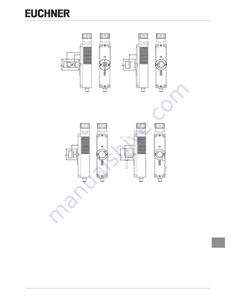
With auxiliary key release
With wire front release
With auxiliary release
With emergency unlocking


