


15
MAN20001437-01-10/21 (translation of the original operating instructions)
Operating Instructions
Transponder-Coded Safety Switch CTM-I2-BP/BR
EN
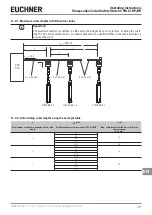
Observe the following requirements with respect to the connecting cables:
For safety switch CTM-…-BP/BR-…-SA-… with plug connector M12, 8-pin
Parameter
Value
Unit
Conductor cross-section, min.
0.25
mm²
R max.
80
W
/km
C max.
120
nF/km
L max.
0.65
mH/km
Recommended cable type
LIYY 8 x 0.34 mm²
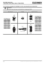
9.5.
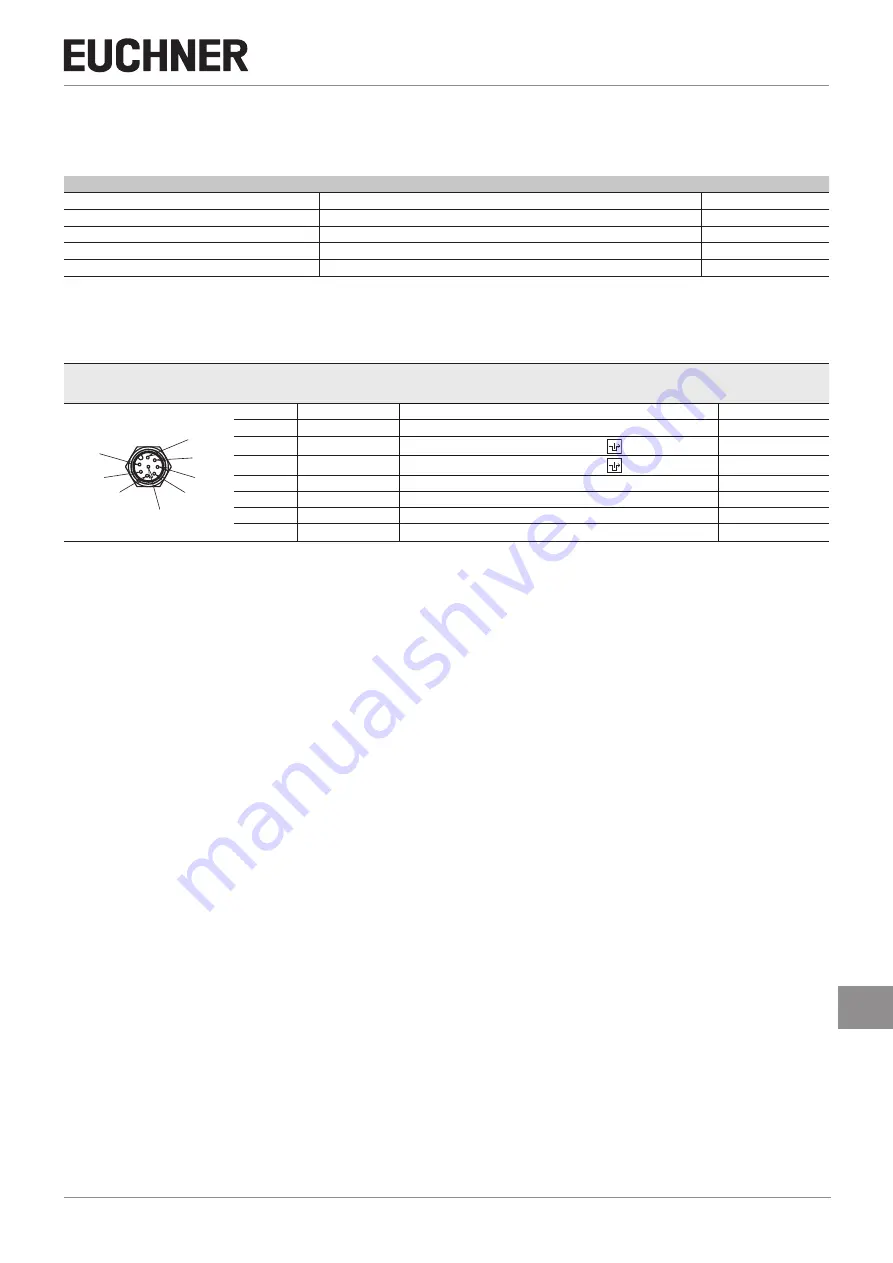
Connector assignment of safety switch CTM-…-BR-…-SA-…
with plug connector M12, 8-pin
Plug connector
(view of connection side)
Pin
Designation
Function
Conductor coloring
of connecting ca-
ble
1)
1 x M12
8
5
6
7
2
4
3
1
1
FI1B
Enable input, channel B
WH
2
UB
Electronics and solenoid operating voltage, 24 V DC
BN
3
FO1A
Safety output, channel A
GN
4
FO1B
Safety output, channel B
YE
5
Ox/C
2)
Door position or guard lock monitoring output/communication
GY
6
FI1A
Enable input, channel A
PK
7
0VUB
Electronics and solenoid operating voltage, 0 V DC
BU
8
IMP
Solenoid control input, 24 V DC
RD
1) Only for standard EUCHNER connecting cable
2) Monitoring output Ox can assume the function OD (door position) oder OL (guard locking). More detailed information about your device is available at
www.euchner.com. Simply enter the order number.
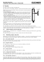
9.6.
Notes on operation with safe control systems
Observe the following requirements for connection to safe control systems:
Ì
Use a common power supply for the control system and the connected safety switches.
Ì
A pulsed power supply must not be used for U
B
. Tap the supply voltage directly from the power supply unit. If the power
supply is connected to a terminal of a safe control system, this output must provide sufficient electrical current.
Ì
The safety outputs FO1A and FO1B can be connected to the safe inputs of a control system. Prerequisite: The input
must be suitable for pulsed safety signals (OSSD signals, e.g. from light grids). The control system must tolerate test
pulses on the input signals. This normally can be set up by parameter assignment in the control system. Observe the
notes of the control system manufacturer. For the test pulse duration of your safety switch, refer to chapter
.
Ì
With series connection: Always connect inputs FI1A and FI1B directly to a power supply unit or to outputs FO1A and
FO1B of another EUCHNER BR device. Pulsed signals must not be present at inputs FI1A and FI1B.
A detailed example of connecting and setting the parameters of the control system is available for many devices at
www.euchner.com, in the area
Service/Downloads/Applications/CTM
. The features of the respective device are dealt with
there in greater detail.
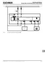
9.7.
Connection without and with IO-Link communication
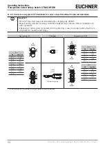
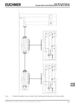
9.7.1. Connection without IO-Link communication
Only the safety and monitoring outputs are switched with this connection method.
With a series connection, the safety signals are looped through from device to device.
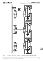
9.7.2. Connection with IO-Link communication
If, in addition to the safety function, detailed monitoring and diagnostic data are to be processed, a BR/IO-Link Gateway
is required. To poll the communication data from the connected device, communication connection C is routed to the BR/
IO-Link Gateway.
You will find further information in the operating instructions for your BR/IO-Link Gateway.


