background image

27330-01A

Installation - Remote Connections

13

Remote Connections

Your sunbed incorporates advanced cir-
cuitry allowing it to connect and commu-
nicate with most remote control systems.
If a remote system is to be used, first
determine whether the remote system is a
T-Max® System or a standard remote sys-
tem operating with a control relay. The
following pages outline many different
remote connection scenarios. Find the
scenario that best fits your application.

Three remote ports are located on top of
the ballast drawer at the front, two RJ-22
(4-wire) ports and one RJ-11 (6-wire)
port. A Remote Control Bypass plug is
already installed in one of the RJ-22
remote control ports. Your sunbed will not
operate without the Remote Control Bypass
plug or a remote system connected.

ATTENTION: Although the Remote
Control Bypass plug provided with your
sunbed will work wherever a T-Max® ter-
minator is called for in the series, the T-
Max® terminator will not work as a
bypass plug. Normally, a bypass plug is
needed only when your sunbed is operat-
ed without a remote system connected.

You will notice some wire clamps along
the side of the fan housing under the
bench. These are for the remote cables to
keep them out from under the ballast
drawer when rolling the drawer in and
out of the unit. Route the remote cables
as shown below, leaving some slack for
the drawer to roll out.

REAR

TO REMOTE
PORT

FAN HOUSING UNDER BENCH

REMOTE PORTS

WIRED

REMOTE

PORTS (RJ-22)

WIRELESS

REMOTE

PORT (RJ-11)

Summary of Contents for STARPOWER 548

Page 1: ...27330 01A...

Page 2: ...under this Standard 48 Month Warranty contact your authorized ETS Distributor or ETS Inc if purchased directly Proof of purchase includ ing serial number is required IN NO EVENT SHALL YOUR DISTRIBUTO...

Page 3: ...rve all safety precautions Safety Information iii Installation 1 Unpacking and Inspection 1 Tools Required 1 Pre Installation Planning 2 Hardware Inventory 2 Assembly Procedures 4 Electrical Connectio...

Page 4: ...let radiation during the first 50 hours of operation Recommended tanning times should therefore be reduced by approximately 10 during that period WARNING Read the instructions booklet before using thi...

Page 5: ...h le initial Les lampes neuves mettent approximativement 10 de plus de rayons ultraviolets au cours des 50 premi res heures de fonction nement Le temps de bronzage doit donc atre r duit d environ 10...

Page 6: ...e After unpacking the unit check to make sure you have received the following Canopy unit Bench unit Rear lamp module Ballast tray Access panel Two large bench endcaps Body fan kit Shoulder tanner kit...

Page 7: ...could cause damage and void the warranty CAUTION Proper assembly of your sunbed requires four people Plan to have a few helpers assist you CAUTION The STARPOWER 548 operates from a 220V AC power sourc...

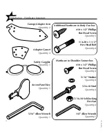
Page 8: ...in Body Fan box 10 x 1 2 Phillips Pan Head Screw Quantity 5 1 4 20 x 1 1 2 Hex Head Bolt Quantity 4 Hardware in Shoulder Tanner box 10 x 1 2 Phillips Pan Head Screw Quantity 4 5 16 Washer Quantity 4 5...

Page 9: ...caps you must install the body fan power cord into the foot end endcap as shown below and the shoulder tanning unit power cord into the head end endcap The connector will snap securely into the endcap...

Page 10: ...tion Assembly Procedures Parts needed Foot end endcap Head end endcap 14 10 x 1 Phillips pan head screws 4 10 x 1 2 Phillips pan head screws Attach endcap with 1 screws as shown Foot end endcap shown...

Page 11: ...Attach adapter arms to canopy arms using two adapter gussets and six bolts and nuts Parts needed Canopy 2 Canopy Adapter Arms 4 Adapter Gussets 12 3 8 x 1 1 4 hex socket bolts 12 3 8 self locking hex...

Page 12: ...sitioning bolt will engage the slot on top of hinge arm and hold canopy up while the other bolts are installed Install other bolts as shown Secure all six bolts in place with self locking nuts Parts n...

Page 13: ...8 Installation Assembly Procedures 27330 01A Parts needed Rear lamp module 8 10 x 1 2 Phillips pan head screws Secure rear lamp module in place with 8 screws where shown Canopy removed for clarity...

Page 14: ...tallation Assembly Procedures 9 27330 01A Parts needed Body fan kit Shoulder tanner kit Install the body fan and shoulder tanner as described in the instruction sheets included in their respective box...

Page 15: ...7330 01A Installation Assembly Procedures Slide the ballast tray under the unit and pull the cords through to the rear Install the access panel by putting it in place and locking with the access panel...

Page 16: ...NFIGURATIONS MAY VARY FROM SHOWN Rear of ballast tray shown Connect the RJ 11 phone type cable between the canopy and rear jack on the ballast tray The three jacks on the front of the tray are for rem...

Page 17: ...aped Lift Adjustment lugs shown below clockwise for more lift and coun terclockwise for less When adjusted properly the canopy should raise easily as well as rest fully closed Always adjust both lugs...

Page 18: ...e of the RJ 22 remote control ports Your sunbed will not operate without the Remote Control Bypass plug or a remote system connected ATTENTION Although the Remote Control Bypass plug provided with you...

Page 19: ...your T Max manual for descriptions of these parameters and how they function REMOTE PORTS WIRED REMOTE PORTS RJ 22 WIRELESS REMOTE PORT RJ 11 T Max Wireless Remote System The T Max AP 900 eliminates...

Page 20: ...a Manager If you re using a 1A in this manner it must have a chip labelled master installed on its circuit board The remote control bypass plug must not be used in this configuration The 3A may be us...

Page 21: ...ting the need to wire the Manager to the tanning beds Scenario 5 T Max Manager Series with Wireless combo 2 Wireless can be easily added to an existing salon already utilizing T Max Connect one AP 900...

Page 22: ...tration below details a typical connection Follow the instructions provid ed with the kit and from the remote s manual to make the necessary connections Setting the sunbed address manually Before conn...

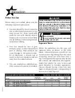
Page 23: ...a base tan may begin at advanced levels corresponding to the extent of their base tan Before You Tan Before using your sunbed please note the following important precautions Your skin should be free o...

Page 24: ...andle do not push up on the acrylic shield The cooling fans run for a period of time after the lamps shut off to aid in cool ing the sunbed The timer will indicate as a reminder to clean the sunbed Af...

Page 25: ...estart with the remaining time otherwise the timer will reset to 0 6 Raise the canopy by using the canopy handle do not push up on the acrylic shield The cooling fans run for a period of time after th...

Page 26: ...ft cloth wipe the entire length of each lamp Step 3 Clean both sides of the acrylic shields with a non ammonia dis infectant cleaner Step 4 Wipe the reflectors with a clean damp cloth Step 5 Reinstall...

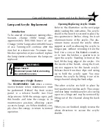
Page 27: ...next page while reading this instruction The acrylic shield in the bench is secured in place by two quarter turn latches along the front aluminum frame of the acrylic The alu minum frame around the ac...

Page 28: ...23 27330 01A Care and Maintenance Lamp and Acrylic Replacement CANOPY ACRYLIC REAR LAMP MODULE ACRYLIC ACRYLIC SUPPORT BENCH ACRYLIC...

Page 29: ...1000 hours of effective tanning use The 160W lamps have an average life of 600 800 hours Lamps used longer than that begin to lose their effec tiveness even though they continue to light Recommended...

Page 30: ...towel Ensure that the lamp is firmly seated in the lamp holders Note Never take hold of the lamp such that your fingers are in contact with the lamp glass Finger oils will greatly reduce the lamp s o...

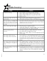
Page 31: ...nt minute is subtracted from the last minute 1 Check that lamp is installed correctly 2 Switch unlit lamp with a lamp that lights if new lamp lights and old lamp still does not replace old lamp 1 Face...

Page 32: ...e on Contact servicer Current sensor indicating unit is on when it should be off Contact servicer Requested session time exceeds maximum time allowed 1 Bypass plug is not installed see Remote Connecti...

Page 33: ...device has not been set 2 The sunbed has not been connected to the remote system see Remote Connections 1 Delay time of T Max Manager has not been set 2 Delay time has expired and session has begun Au...

Page 34: ...27330 01A E548R canopy cover removed and electrical shields cut back...

Page 35: ...27330 01A Shoulder Tanner outside shroud removed...

Page 36: ...27330 01A Body Fan...

Page 37: ...27330 01A Ballast Tray...

Page 38: ...Head End Fan 6 Fan Round Fan Square Filter Handle Kit Hardware Kit Assembly Hardware Kit Canopy Hour Counter Ignitor Lamp Holder w Starter Lamp Holder w o Starter Lamp Holder Face Tanner Lamps Panel L...

Page 39: ...uts bolts etc I Check Power Cords J Change Filters See Care and Maintenance See Lamp and Grill Replacement See Final Adjustments Fans are located on top of the canopy under the bench in the shoulder t...

Page 40: ...page iii BRONZING SUN PLUS Velocity VS R Ballasts 100W bench 160W canopy Face Tanner SolarMax IFT FT Ballasts 400W Cooling System 825cfm body fan at foot end 220cfm fan at head end Timer System Digit...

Reviews: