5.
Establish a reference level by decreasing the attenuation level until the
signal can be detected by the receiver. Note the attenuator setting.
6.
Relocate antennas so that the screen room wall is between them.
7.
Reduce attenuation further until signal is again seen at the same level
as without shielding.
The difference in the two attenuator settings is the shielding effectiveness. If the
signal cannot be seen with a zero setting, then the shielding effectiveness is
greater than the attenuation range or the power amplifier does not have enough
power.
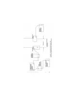
Suggested Test Setup Diagram
on page 22.
The table on page 24 shows the maximum shielding effectiveness measuring
capability of the Model 3305 E-Field Shielding Effectiveness Test Kit and the
approximate wattage required for the Model 3303 Rod Antenna to meet the
minimum shielding requirements of NSA 65-6.
These shielding effectiveness readings are valid only if the power
amplifier is operating in the linear region. This can be verified by
reducing (or increasing) attenuation and observing the receiver signal
on the analyzer or receiver. If the receiving signal also decreases (or
increases) by the same amount then the amplifier is operating in the
linear region.
Suggested Test Setup Diagram
See next page for diagram.
22
|
Model 3305 Suggested Test Setup
Summary of Contents for 3303
Page 1: ...Model 3303 Rod Antenna User Manual Model 3303 Antenna Base ...
Page 7: ...Introduction 7 ...
Page 14: ...This page intentionally left blank 14 Specifications ...
Page 23: ...Model 3305 Suggested Test Setup 23 ...
Page 26: ...This page intentionally left blank 26 Model 3305 Suggested Test Setup ...
Page 27: ...6 0 Typical Data Typical Data 27 ...
Page 28: ...28 Typical Data This page intentionally left blank ...


