5.0 Model 3305 Suggested Test Setup
Before connecting any components, follow the
safety information in the ETS-Lindgren
Product Information Bulletin
included with your
shipment.
Measuring Electronic Field Shielding Effectiveness
Reduce amplifier power to zero watts before
band switching the Model 3303.
Reference:
•
NSA
65-6
•
MIL-STD-285
1.
Place the transmitting and receiving antennas so that they are
24 inches plus the thickness of the screen room wall apart from each
other.
2.
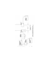
Set up equipment as shown in
Suggested Test Setup Diagram
on
page 22.
3.
Turn generator to ON position.
Disable RF output of generator.
Turn amplifier to ON position.
Turn receiver to ON position.
Turn Model 3301C power on.
Set receiver.
Set the attenuator at maximum (100 dB–150 dB) attenuation.
Enable RF output of the generator.
4.
Adjust signal amplitude on signal generator to maximum allowed by
amplifier input.
Model 3305 Suggested Test Setup
| 21
Summary of Contents for 3303
Page 1: ...Model 3303 Rod Antenna User Manual Model 3303 Antenna Base ...
Page 7: ...Introduction 7 ...
Page 14: ...This page intentionally left blank 14 Specifications ...
Page 23: ...Model 3305 Suggested Test Setup 23 ...
Page 26: ...This page intentionally left blank 26 Model 3305 Suggested Test Setup ...
Page 27: ...6 0 Typical Data Typical Data 27 ...
Page 28: ...28 Typical Data This page intentionally left blank ...


