TABLE OF CONTENTS
Page number
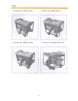
Overall
view
of
the
generator
set
4
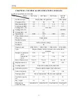
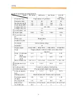
Chapter 1 Technical Specifications and Data
5
1-1
Technical
specifications
and
data
5
1-2
Basic
operating
parameters
7
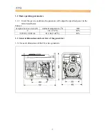
1-3 General dimensions and overview of the generators
7
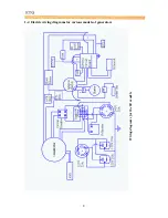
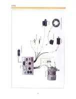
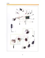
1-4 Electric wiring diagrams for various models of generators
8
Chapter 2 Operating the Diesel Generator
11
2-1 Main points of safety during operation of the generator
11
2-2
Preparation
before
operation
13
2-3 Checking the operation of the diesel engine
16
2-4
Starting
the
generator
set
16
2-5 Procedures for starting the generator set
19
2-6 Proper operation of the generator set
21
2-7
Loading
21
2-8
Stopping
the
generator
23
Chapter 3 Maintenance
24
3-1
Maintenance
schedules
24
3-2 Storing for long periods of time
26
Chapter
4
Troubleshooting
27
4-1 Overhauling and troubleshooting procedures
27
4-2
Questions
and
doubts
27
Chapter 5 Generator Parts Diagrams and Listings
28
Limited Warranty
34
Product
Registration
Card
34
List for comments from users
36
Appendix
37
1. Attached list of tools fittings, and subassemblies
37
2.
Attached
technical
documents
37
3
Summary of Contents for 170F
Page 1: ...OWNER S MANUAL AIR COOLED DIESEL ENGINE 170F FE FS FSE 178F FE FS FSE 186F FE FS FSE 1 ...
Page 12: ...1 2 Diesel Engine shaft specifications units mm 12 ...
Page 13: ...Sizes of PTO flanges Diesel Engine Power Curves 1 4 Names of Diesel Engine Parts 13 ...
Page 20: ...20 ...
Page 26: ...26 ...
Page 29: ...CHAPTER 4 PART LISTINGS Diesel Engine Exploded View 29 ...
Page 32: ...Fig 4 1 Exploded view of engine block assembly 32 ...
Page 35: ...Fig 4 2 Exploded view of cylinder head 35 ...
Page 38: ...Fig 4 3 Exploded view of Piston Crank Assembly 38 ...
Page 40: ...Fig 4 4 Exploded view of fuel tank parts 40 ...
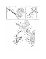
Page 43: ...Fig 4 5 Lubrication and speed control system 43 ...
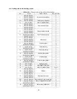
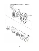
Page 46: ...Fig 4 6 Exploded view of cooling and recoil starting system 46 ...
Page 49: ...49 ...
Page 52: ...OWNER S MANUAL Air cooled diesel engine generator set DG4LE DG6LE 1 ...
Page 60: ...9 ...
Page 61: ...10 ...
Page 71: ...20 ...
Page 80: ...29 Figure 5 3 Exploded view of frame assembly ...


