background image


Exit: exit “counterpoint operation” interface, enter “operation interface”, current state have no change. 

When working area display aligning arm in, then status bar location of aligning arm: external; 

When working area display vacuum open, then vacuum state in status: “close”. 

 
When status bar display “high speed mode”, express move speed is high, when status bar display “low 

speed mode”, express move speed is low. This function effect in counterpoint interface. 


11.3 parameter testing interface 

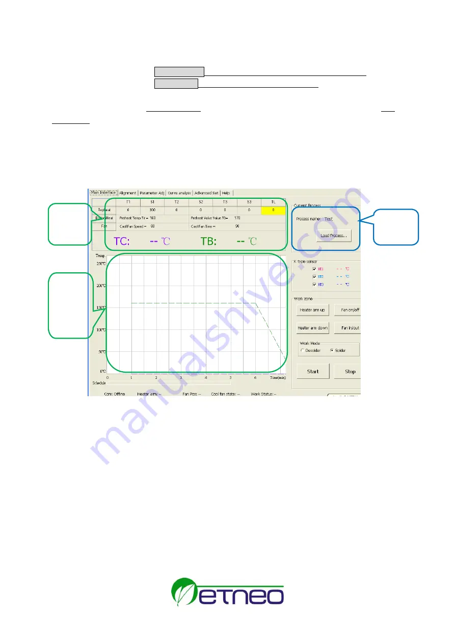
Parameter testing interface: when solder or desolder new chip, by this display, we can do solder or desolder 

testing. 


Counterpoint height: memory setting height. After setting, auto memory this height, the same 

specification chip counterpoint, call save flow, do not need adjust counterpoint height. 

Counterpoint height cancel: cancel saved counterpoint height. 

Suck height: memory sucking height which have be set. After setting, auto memory this height, when 

suck the same chip next time, we can call the saved flow, not need adjust counterpoint 

height. 

Cancel suck height: cancel suck height which have be saved. 

In flow edit display, show goal flow name and technology type

desolder/solder

nozzle size

down 

distance and heat dissipation air quantity etc.   

Down  distance:  adjust  heat  head  height  range,  setting  range  0~255mm;  heat  dissipation  air  quantity 

setting range 35~100. (can adjust on the basis of PCB adjust) 

After  edit  parameter  in  parameter  setting  display,  in“flow  edit  display”input  flow  name,  appropriate 

nozzle size, select flow technology curve is “desolder”

or “solder”. And then click “parameter save” and 

Parameter 

testing 
display   


Flow edit 

display 


Parameter 

testing 
display   


Summary of Contents for BGA ETA-H15

Page 1: ...stem 5 6 2 Install RPC 5 6 3 System Connecting 5 7 control box Instructions 6 8 IR System Operation 7 8 1 Part Function 7 8 2 Parameters Setting 7 8 3 Operating technics instruction 15 9 PL System Operation 17 9 1 Component function 17 9 2 Aligning Technics 18 10 Equipment Maintenance 19 11 QSOFT brief instruction 1 11 1 operation interface 1 11 2 counterpoint operation interface 2 11 3 parameter ...

Page 2: ......

Page 3: ...nfrared heater has a well proportioned and safe heating and power and flexibleness necessary for the system so it can also deal with some PCBs with big thermal capacity and other high temperature situation lead free soldering easily The adjustable aperture under the infrared heater can protect the adjacent components which are sensitive to the temperature on PCB from being heated No need for nozzl...

Page 4: ...ture card BGA tool box computer LCD optional 4 Safety Instructions Note For safety of system and operator please read this manual carefully before operating the unit Please note that the unit is suitable for soldering and de soldering of electronic components Note Top and bottom IR radiator will be very hot during working so explosive and combustible object or gas and solvent is strictly prohibite...

Page 5: ... Preheating Time of Bottom Heater about90s size 260 260mm 5 Top heater range size 20 60mm 6 Vacuum Pump 12V 300mA 0 05Mpa 7 Top cooling Fan 24V 300mA 15CFM 8 Laser Alignment Tube 5V 30mA 2pcs 9 LCD Display Screen 65 7 23 5 mm 16 2 character 10 Communication Standard USB connector Connect with PC 11 Movable Motor stepping motor 12 Movable Arm Range 135mm 13 Infrared Temperature sensor 0 300 Testing...

Page 6: ...erature of bottom heater TC The real time temperature of top heater S1 Heating time rising from T1 to T2 S2 Heating time rising from T2 to T3 S3 Heat preservation time of T3 IR ETA H15 Rework System has ten working modes and its parameter can be changed according to demand The following eight data can be referred 0 T1 120 S1 50s T2 140 S2 45s T3 195 S3 15s TL 183 TB 150 T0 100 1 T1 130 S1 40s T2 1...

Page 7: ...ob in corresponding direction and then adjust RPC can be moved up and down or turned 6 3 System Connecting Please check whether the supply voltage accords with the rated voltage on the system nameplate Please check whether all switches are turned off Connect the video cord of outside Indicator or Monitor to the VIDEO OUT socket Connect IR camera RPC to IR camera socket Connect control box to socke...

Page 8: ...top IR heater move up and down C Function of OK key Make the BGA IR enter parameters setting mode and cursor move a step forward D Function of cool stop key if BGA IR in flow stop and finish flow if BGA IR in flow open or close cool fan E Function of START key in standby state make BGA IR enter solder and desolder F Function of in out suck key cool fan stretch out or retraction PL system Key G Fun...

Page 9: ...nd tighten them Note Adjusting the aperture system can protect the adjacent components on the PCB from being heated But when the aperture system is adjusted to small size the Top Radiator will be very hot and decrease its lifetime so it s necessary to increase the window size appropriately to avoid the damage of the Top Radiator 8 2 Parameters Setting Parameter settings order as the follows A _pas...

Page 10: ...00 of system Press MENU Press MENU rotate MENU Press MENU 旋转 rotate MENU Press MENU rotate MENU Press OK After input password 1 If you want to modify the password return to above mode to input the new password If password is modified successfully it will show TC 022 C Tb 019 C ready for flow _password select 0 password select 0 password 0 select 0 password 0 select 0 password 00 select 0 password ...

Page 11: ... if press SET key you can browse and modify parameter of this flow shown as C 1 item 2 After finishing modifying of working flow 1 if you want to modify the next working mode operate as C item shows If you don t want to modify it you can press DOWN knob to browse the next parameter settings C Modify working mode For instance Modify the working mode and make it in desolder mode rotate MENU Press ME...

Page 12: ...TB The test temperature of bottom preheating TIR set temperature of bottom heating TC Real time temperature of top heating T1 It is the heat preservation starting temperature of reflow soldering It is the second temperature of this technics process The temperature rises to T1 with a proper speed the component permits In parameter modifying use the UP and DOWN knob to set the value of T1 T2 It is t...

Page 13: ...oose K type sensor used for measuring temperature besides system s IR sensor The signal of chosen sensor will be displayed and used for process controlling In parameter modifying use the UP and DOWN key to set the value Password It is used for setting password It is designed for preventing the equipment unnecessary or non authorized change When it is set to 000 the password protecting is useless T...

Page 14: ...NU Press MENU Press MENU rotate MENU Press OK Press MENU Press MENU Press MENU T1 130 _S1 060s T1 130 S1 060s S1 070s T2 150 S1 070s T2 150 S1 060s T2 150 S1 060s T2 160 T1 130 S1 060s T1 130 S1 070s T1 130 S1 070s S1 060s T2 160 T2 160 S2 030s T2 160 S2 030s T2 160 S2 030s T2 160 S2 050s ...

Page 15: ...ress MENU Press MENU 按下 MENU rotate MENU Press OK rotate MENU rotate MENU rotate MENU Press OK TL 183 TB 140 T0 090 T FAN 100S T FAN 100S SPD 80 T2 160 S2 050s S2 050s T3 200 T3 200 S3 010s S3 010s TL 183 TL 183 TB 140 TL 183 TB 140 TL 183 TB 130 TL 183 TB 130 TB 130 T0 090 TC 022 C Tb 019 C ready for flow ...

Page 16: ...Now the system has saved all parameter settings IR window will display 3 After all technics parameters have been selected press BEGIN key and the system perform the set flow E System Error Indication 1 In initial state if the top sensor or outer sensor is broken it displays If the bottom sensor is broken it displays select 1 type desolder type desolder laser off type desolder laser off type desold...

Page 17: ... Heater will be very hot during working so please don touch the hot housing parts Note The laser alignment device includes a secondary laser device so don t see the laser bean directly 8 3 1Soldering Technics 1 Turn on power switch of each part 2 Move PCB Fixture with fixed PCB and make it above the Bottom Radiator and make the soldered component on the PCB between Top Radiator and Bottom Radiator...

Page 18: ...e downwards near to bottom B After the system sounds unvaryingly the top heater move upwards and Top Cooling Fan and Outside Cooling Fan spread out to blow cooling air simultaneously C After 150 seconds the two Cooling Fns stop blowing and the soldering technics has been finished 8 3 2 De soldering Technics 1 Turn on power switch of each part 2 Fix the PCB on the top of Bottom Heater and make the ...

Page 19: ...ling fan and Outside Cooling Fan spreads out to blow cooling air simultaneously 15 90 seconds after the top heater starts moving upwards the vacuum suction tube looses component automatically 16 After the two Cooling Fans blow cooling air for 150 seconds the whole de soldering process will be over 9 PL System Operation 9 1 Component function 1 Crosswise Cooling Fan Besides the existing top cooling...

Page 20: ...nscrew Fixed Knob in corresponding direction and then adjust RPC can be moved up and down or turned 5 PL Camera It needs to use PL camera during the component aligning PL camera will transmit the image of soldering point on PCB and component pins under nozzle to Display or Monitor through video signal and user can see these images on Display or Monitor At the moment you can use each adjusting func...

Page 21: ...7 Align the component with two Adjustment Knobs and two Micro adjustment Knobs Make the images of component solder pins and the soldering point on PCB overlap 10 Equipment Maintenance Remark For ensuring reliable function and maintenance of equipment please use parts provided by original factory Please turn off power switch of each part and pull out power plug when not in use Note After cutting of...

Page 22: ...lay temperature Flow curve display window temperature curve of KT1 KT3 easy to real time watch and curve analysis Flow status bar this bar display flow status by colour colour is corresponding to working colour Status bar real time display current state contain communicate state online offline the location of heat head up middle down aligning arm location external middle interior head dissipation ...

Page 23: ...duce picture focus Heat arm up click heat arm move up press on continuous heat arm move up continuous Heat arm down click heat arm down press on continuous heat arm move down continuous Suck component place component click then suck component after suck show place component and then click this button place component button display change to suck component Vacuum open vacuum close open or close vac...

Page 24: ...save flow do not need adjust counterpoint height Counterpoint height cancel cancel saved counterpoint height Suck height memory sucking height which have be set After setting auto memory this height when suck the same chip next time we can call the saved flow not need adjust counterpoint height Cancel suck height cancel suck height which have be saved In flow edit display show goal flow name and t...

Page 25: ...perature of this flow temperature rise slope temperature change of every heat process and time thus judge if correspond technology flow 2 In curve analysis interface can save or delete current curve or call saved curve analysis and also print current curve file 3 After open flow file flow curve interface auto display flow curve if flow file contains external K type temperature test data then displ...

Page 26: ... The people who obtain parameter protect can operation this software and modify parameter If not set parameter protect password people who obtain enter password also modify parameter Color of K type temperature curve setting provide different color and curve wide In technology interface temperature display by curve different color express different K type temperature sensor ...

Reviews:

Related manuals for BGA ETA-H15