background image

9

www.etna.com.tr

30A Relay

U  V  W
MOTOR

POWER

POWER

INPUT

FL

O

ATER

PRES

SURE

SWIT

CH

CO

M

RU

N

FA

U

LT

L1  L2  L3

Pe

30A Relay

TRANSFORMER

HYDROPAN 1

30A Relay

TR

30A Relay

U  N

MOTOR

POWER

POWER

SUPPLY

FL

O

ATER

PRES

SURE

SWIT

CH

CO

M

RU

N

FA

U

LT

N  L1 

Pe

30A Relay

TRANSFORMER

HYDROPAN 1

30A Relay

TR

U  N

MOTOR

POWER

POWER

SUPPLY

N  L1 

30A Relay

U  V  W
MOTOR

POWER

POWER

INPUT

PRES

SURE

SWIT

CH

CO

M

RU

N

FA

U

LT

WELL

L1  L2  L3

Pe

30A Relay

TRANSFORMER

HYDROPAN 1

30A Relay

TR

30A Relay

PRES

SURE

SWIT

CH

CO

M

RU

N

FA

U

LT

WELL

Pe

30A Relay

TRANSFORMER

HYDROPAN 1

30A Relay

TR

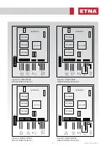
Figure 13. THREE PHASE

Deep Well Mode Connection

Figure 15. SINGLE PHASE

Deep Well Mode Connection

Figure 12. THREE PHASE

Booster Mode Connection 

Figure 14. SINGLE PHASE

Booster Mode Connection

Summary of Contents for Hydropan

Page 1: ...Hydropan Single with Alarm Kit Operation and Maintenance Manual...

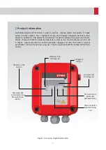
Page 2: ...witch Fault warning leds as well as Up Down buttons used to surf in menus Approval button to confirm parameter changes and ON OFF button System parameters can be set easily by using Up Down Approval b...

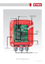
Page 3: ...3 www etna com tr Connectors Cable Glands Voltage Transformer 7 Segment Display Connection Cable Current Transformers Power Relays Earth Connection Bar Figure 2 Hydropan Single Internal View...

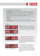
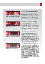
Page 4: ...rrent Protection Setting High Current Protection Setting Current and Voltage fault delay time setting General Fault Dry Running and Pressure Switch signal warning leds Pump running currents display on...

Page 5: ...wer supply on the system Voltage value between L1 L2 L3 and neutral is displayed in sequence as seen on the right hand side when there is no signal from pressure switch In case there is signal from pr...

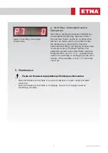
Page 6: ...in screen It is possible to enter the submenu by re pressing the Approval button and fault display delay duration value can be set by using Up Down buttons Pump Operation Mode Selection Menu as P6 see...

Page 7: ...s active when Pump Operation Mode parameter set to 1 or 2 requested time duration for well filling or discharging can be set in minutes If this parameter is set to 0 it becomes out of use Figure 11 We...

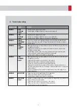
Page 8: ...otor label Check motor cable and connector connections ERROR 5 LOW CURRENT FAULT Before performing any measurement make sure there is no mechanical congestion in pump Make sure that pump suction valve...

Page 9: ...N 1 30A Relay TR U N MOTOR POWER POWER SUPPLY N L1 30A Relay U V W MOTOR POWER POWER INPUT PRESSURE SWITCH COM RUN FAULT WELL L1 L2 L3 Pe 30A Relay TRANSFORMER HYDROPAN 1 30A Relay TR 30A Relay PRESSU...

Page 10: ...Dudullu Organize Sanayi B lgesi 2 Cadde No 14 34775 mraniye stanbul Turkey Tel 90 216 561 47 74 Pbx Fax 90 216 561 47 50 www etna com tr en info etna com tr customer service...

Reviews: