15
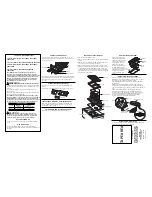
Position the clips as shown in the diagram,
fastening them to the openings in the lower
part of the body using the screws provided.
For worktop thicknesses of 30 mm. or less,
use the self-tapping screws that are provi-
ded as a fastening accessory - put them
into the clip’s round hole. This hole will be
threaded as the screw is inserted into it,
and this should be done before fixing the
clip to the worktop.
Connecting the electricity
Before connecting the hob to the electric
mains, check that the voltage and fre-
quency of the mains matches what is
shown on the hob’s rating plate, which is
located lower down, and on the guarantee
certificate or, where appropriate, the tech-
nical datasheet supplied, which should be
kept together with this manual.
The electric connection is made via an
omnipolar switch or plug where accessi-
ble, which is suitable for the intensity to be
tolerated and which has a minimum gap of
3 mm between its contacts, which will
ensure disconnection in case of emer-
gency or when cleaning the hob.
The connection should include correct ear-
thing, in compliance with current norms.
Avoid that the cabling remain in contact
with neither the casing of the hotplate nor
that of the oven.
Joining the hob to the oven
1
Disconnect the electricity.
2
Partially place the oven in its position.
3
Plug in the connection(s) between the
cooker and the oven (see fig. 3) to con-
nect both appliances.
Make sure the
connectors fit completely in its soc-
kets and the intersection haven’t cau-
sed the exit of any of the terminals.
To check this, pull slightly the cables,
one by one, making sure they have all
kept in.
4
Finish inserting the oven into its definiti-
ve position.
Rear view of the A6405 oven:
The instruction manual indicates
how the oven must be positioned as well as
how the electrical connectors must be set
up. Before accessing the interior of the
appliance, it must be disconnected from the
power outlet.
40 mm
20/30 mm
fig. 2
Self-tapping screw for 20
and 30 mm thick worktops
Sealing joint
Sealing joint
GB
fig. 3


