background image

Q u i c k   G u i d e :

Unison AV/Serial Interface v1.1.0 Quick Guide

Unison AV/Serial Interface v1.1.0 Quick Guide

Page 4 of 10

Electronic Theatre Controls, Inc.

of some other event in Unison, or monitoring a zones level).

Communication between the station and the serial host

• Use a standard RS232 straight-through cable.
• Station 9 pin “D style” connector pinout: pin 2 - transmit data (TX), pin 3 - receive data (RX), 

pin 5 - Common

• Com port settings are 9600 baud, 8 bits, no parity 1 stop bit, and Xon/Xoff flow control.

Station Configuration with a Computer Example

• Connect your computer to the station with a standard RS232 straight-through cable.

Station 9-pin “D” style connector pinout: pin 2 - Transmit data (TX), pin 3- Receive data 

(RX), pin 5 - Common.

• Use a communications terminal application, such as Hyper Terminal, to interface with the 

station.

• Com port settings are 9600 baud, 8 bits, no parity, 1 stop bit, and Xon/Xoff flow control.

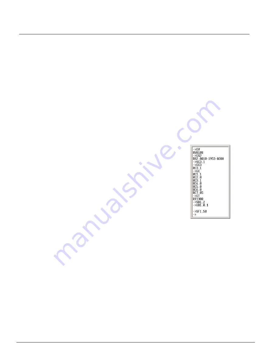
Sample commands: 

Commands are terminated with carriage return:

• SC 1.1 (Turn on echo mode)

You won't see anything when you type until echo mode is 

turned on. Default is off - see 

Configuration Settings (nn.cf) 

on page 7

)

• GV (Get version number) 

See 

Protocol Version (pv) on page 6

)

• GS2 (Get neuron ID) 

See 

Station Status (ss) on page 6

)

• SC3.1 (Set level and fader scale to 0-100, or percentages)
• GC3 (Get configuration index 3's value)
• GC (Get all of the configuration values) 

See 

Configuration Settings (nn.cf) on page 7

)

• GT (Get the station type) 

See 

Station Type (st) on page 8

)

• SB1.2 (Set button 1 - execute a toggle) 

See 

Button States (bs) on page 5

)

• SF1.50 (Set fader 1 to a level of 50) 

See 

Level (ll) on page 6

 an

Fade Rate (rr.dd) on page 6

)

Summary of Contents for Unison AV/Serial Interface v1.1.0

Page 1: ...late the virtual buttons faders and rates with serial commands Presets macros or other Unison station events may be activated or deactivated using this station Feedback information is passed back in t...

Page 2: ...ethod or by sending a specified serial command to the device In this mode commands that set the LED state for buttons 1 thru 16 result in activation of macros 101 thru 116 on the serially connected Em...

Page 3: ...nd the PC Interface station have different electronics and are not interchangeable In addition the AV Serial interface station must include neuron code v1 4 or later to function properly with Light Ma...

Page 4: ...ta RX pin 5 Common Use a communications terminal application such as Hyper Terminal to interface with the station Com port settings are 9600 baud 8 bits no parity 1 stop bit and Xon Xoff flow control...

Page 5: ...nd F Fader U Update An automatic system response initiated by a status change of an item on the station such as a button s LED turning on L Level M Memory R Rate S Status T Type V Version Object Get C...

Page 6: ...nstalled bound Bit Description 0 Station reset occurred 1 Station wink occurred 2 A command error occurred 3 UART error occurred 4 5 Unison install status 00 unistalled 01 installed 10 bound 6 15 Unus...

Page 7: ...off set levels to 0 and clear bindings Notes Configuration switches are stored in EEROM and are retained during a power loss When packet mode is enabled commands are prefixed with a one byte preamble...

Page 8: ...the button and fader mapping to a physical station faders are numbered right to left and buttons 1 10 are on the right side of the faders and 11 12 are on the left The AV Serial Interface station s b...

Page 9: ...matically if there is only single station of that type in the Unison configuration Additional Notes Comments Single Byte Commands The Cancel command flushes command buffer and cancels Xoff command SF0...

Page 10: ...type the preamble character by holding the Alt key while typing the 4 digit number listed while using a terminal emulator such as Hyper Terminal You will see the display character if you have local ec...

Reviews: