background image

ETC, Source Four, Revolution, and QXL are registered trademarks of Electronic Theatre 

Controls, Inc. in the United States and other countries. 

Other product and company names mentioned herein may be trademarks and/or service marks 

of their respective owners.

The Source Four Revolution fixture is protected by one or more of the following patents, and 

other pending patent applications worldwide:

US Patent # 6,628,089 B2, 6,932,491, 6,979,106, 6,902,302, 6,939,026, 6,903,531, 7,033,047 

and US Design  Patent #D477,885 S

USRE36,316

GB05952589

DE0592589

JP2,501772

Patents Pending

ETC intends this document, whether  printed or electronic, to be provided in its entirety.

ACCREDITATIONS AND RECOGNITIONS (from ETL SEMKO : 

www.usa.etlsemko.com

)

ETL SEMKO is recognized by OSHA in the U.S. as a Nationally Recognized Testing Laboratory. 

ETL tests to standards developed or approved by the American National Standards Institute 

(ANSI), Underwriters Laboratories (UL) and others.  Other notable accreditations include the 

American Association of Laboratories Accreditations (A2LA), American National Standards 

Institute (ANST), International Conference of Building Officials (ICBO), and the International 

Electrotechnical Commission of Electrical Equipment (IECEE). ETL also has accreditations and 

recognitions from around the globe. Visit 

www.etlsemko.com/accred.html

 for a complete listing. 

Summary of Contents for Source Four Revolution

Page 1: ...s Inc All rights reserved Product information and specifications subject to change Part Number 7160M1210 Rev B Released November 2007 The Source Four Revolution high performance automated ellipsoidal spotlight is intended for professional use only Read entire User Manual before using equipment ...

Page 2: ...tends this document whether printed or electronic to be provided in its entirety ACCREDITATIONS AND RECOGNITIONS from ETL SEMKO www usa etlsemko com ETL SEMKO is recognized by OSHA in the U S as a Nationally Recognized Testing Laboratory ETL tests to standards developed or approved by the American National Standards Institute ANSI Underwriters Laboratories UL and others Other notable accreditation...

Page 3: ...figuration 15 Removing and Replacing Modules 16 Blank Module BM 17 Iris Module IM 18 Shutter Module SM 19 Static Wheel Module SWM 20 Controlling the Static Wheel Module 20 Rotating Wheel Module RWM 21 Controlling the Rotating Wheel Module 22 Replacing Gobos and Filters 23 Routine Maintenance 25 Procedures 26 Scroller Cartridges and Beam Containment Devices 26 Gel Strings 28 Internal Media Frame IM...

Page 4: ...ture 95 of visible light reflected through the optical train Tool free lamp centering X Y and peak flat Z adjustment knobs Standard Features Integral Pulse Width Modulated 0 77VAC Dimmer Integral 24 frame color scroller with a quick change scroller cartridge ships with the ETC 12 color standard gel string 540 Pan 270 Tilt Accessory slot with retainer Zoom Optics Internal Media Frame for insertion ...

Page 5: ... modules which can be fitted with gobos or dichroic color filters If you have questions about your Source Four Revolution fixture that are not answered in this manual please contact the supplier of your ETC equipment or ETC Technical Services Please email comments about this manual to TechComm etcconnect com Americas United Kingdom Electronic Theatre Controls Inc Electronic Theatre Controls Ltd Te...

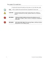
Page 6: ...AUTION A Caution statement indicates situations where there may be undefined or unwanted consequences of an action potential for data loss or an equipment problem WARNING A Warning statement indicates situations where damage may occur people may be harmed or there are serious or dangerous consequences of an action WARNING RISK OF ELECTRIC SHOCK This warning statement indicates situations where the...

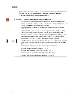
Page 7: ... a suitable structure using a minimum of two hook clamps secured with tightened steel bolts 12 mm 1 2 Ø washers and locking nuts In addition to primary suspension attach a safety cable ETC Model 400SC or other approved safety cable or device to the handles of the fixture s upper enclosure Always replace the lamp if it becomes damaged or thermally deformed Keep the luminaire at least 0 7m 28 away f...

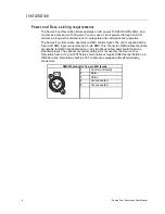
Page 8: ...nal The unit is supplied with a 5 pin XLR DMX input connector and a 5 pin DMX Thru connector DMX cables should be acceptable for DMX data transmission not microphone cable and should follow the standard pinout The optional secondary data pair is not used by the Source Four Revolution fixture On pre 2007 fixtures termination is required after the last fixture on a DMX data line Revolutions built in...

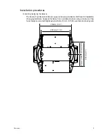
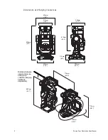
Page 9: ...ixture s upper enclosure provides six bolt holes for installation of hanging hardware Suspend the fixture from a suitable structure using a minimum of two hook clamps secured with tightened steel bolts 12 mm 1 2 Ø washers and locking nuts 330mm 13 0 295mm 11 6 123mm 4 85 246mm 9 7 123mm 4 85 ...

Page 10: ...ensions and Hanging Clearances 344mm 13 5 317mm 12 5 454mm 17 9 394mm 15 5 400mm 15 7 619mm 24 4 116mm 4 6 856mm 33 7 762mm 30 0 775mm 30 5 713mm 28 1 856mm 33 7 Distance between upper enclosure and pipe is variable hanging hardware dependent ...

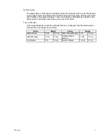
Page 11: ...ve as little slack as possible in the safety cable to avoid the cable catching the yoke of the fixture Fixture Weight Total weight depends on how the individual fixture is configured Use the table below to calculate the total weight of your fixture Device Weight Device Weight Base Fixture 74 lb 33 6 kg Static Wheel Module 3 lb 1 4 kg Blank Module 1 8 lb 0 7 kg Rotating Wheel Module 3 7 lb 1 7 kg I...

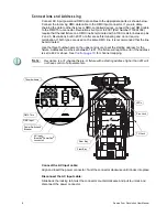
Page 12: ...t the line be terminated Use the three thumbwheels on the upper enclosure to set the starting address for the fixture Addresses must be set between 1 481 The fixture will report an error if the address is set to 482 or above See Control page 10 for channel mapping Note Revolution is a 31 channel fixture A fixture with a starting address higher than 481 will not have control of all parameters Conne...

Page 13: ...ation process has completed the fixture s motors will end in the position determined by the incoming DMX signal If no signal is present the fixture s functions will rest at the position of a DMX level of zero Power down Procedure Move the power switch breaker to the off position It is recommended that you allow the fixture to run for at least five minutes with the lamp off prior to removing power ...

Page 14: ...ocus B 8 Zoom Zoom Zoom B 9 Focus Timing F Focus Timing F Focus Timing F 10 Color Timing C Color Timing C Color Timing C 11 Beam Timing B Beam Timing B Beam Timing B 12 Reset Reset Reset 13 Gel Scroller Gel Scroller Gel Scroller C 14 Fan Speed Control Fan Speed Control Fan Speed Control 15 Iris Iris B 16 Front Bay Wheel Position Front Bay Wheel Position B 17 Front Bay Wheel Function Front Bay Whee...

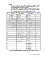
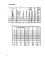
Page 15: ...8 67 63 148 172 160 9 R361 Hemsley Blueb b Rosco donates the proceeds for Hemsley Blue to the Hemsley Foundation 67 76 72 172 195 183 10 R83 Medium Blue 76 85 81 195 219 207 11 R26 Light Red 85 94 90 219 242 230 12 R89 Moss Green 94 100 100 242 255 254 Frame Percent Start Percent End Percent Center Frame DMX Start DMX End DMX Center Frame 1 0 3 0 0 8 1 2 3 10 6 8 25 17 3 10 16 13 25 41 33 4 16 22 ...

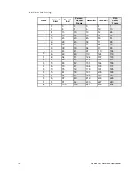
Page 16: ...2 26 4 13 18 15 32 45 39 5 18 23 20 45 58 51 6 23 28 25 58 71 65 7 28 33 31 71 84 78 8 33 38 36 84 97 90 9 38 43 41 97 110 104 10 43 49 46 110 124 116 11 49 54 51 124 137 130 12 54 59 57 137 151 144 13 59 65 62 151 164 158 14 65 70 67 164 178 171 15 70 75 72 178 191 185 16 75 81 78 191 205 198 17 81 86 83 205 219 212 18 86 91 89 219 233 226 19 91 97 94 233 247 240 20 97 100 100 247 255 254 ...

Page 17: ... 26 36 32 5 14 18 16 36 47 42 6 18 22 20 47 58 53 7 22 27 25 58 68 63 8 27 31 29 68 79 74 9 31 35 33 79 90 84 10 35 39 37 90 101 96 11 39 44 42 101 112 106 12 44 48 46 112 123 117 13 48 52 50 123 134 129 14 52 57 55 134 145 140 15 57 61 59 145 156 151 16 61 65 63 156 168 162 17 65 70 68 168 179 174 18 70 74 72 179 191 185 19 74 79 77 191 202 196 20 79 84 81 202 214 208 21 84 88 86 214 225 219 22 8...

Page 18: ...nnels can create unexpected luminaire behavior Step 4 Repeat for other parameter channels and timing channels as needed Fan Speed Control Channel The Fan Speed Control Channel Channel 14 allows fan speed control for quieter fixture operation As long as this channel is at 0 all fans will run at full speed for maximum cooling Setting this channel at incrementally higher values lowers the fan speed i...

Page 19: ...tion total range of motion 90 On board auto sensing electronics Static Wheel Module SWM Four positions typically setup as three positions plus open Gobos or dichroic color filters Uses M sized gobos glass or metal On board auto sensing electronics Rotating Wheel Module RWM Three positions plus open Rotating indexable gobos Uses M sized gobos glass or metal On board auto sensing electronics Module ...

Page 20: ...o the center bay divider Step 2 Guide the module gently into the bay making certain that the guide posts of the module housing are properly aligned with the accommodating hole in the fixture frame Ensure that the module seats on the control card Step 3 Tighten the screws securing the module by turning them to the right clockwise Ensure that the screws are tightened completely CAUTION Prolonged use...

Page 21: ... Blank Module BM The Blank Module is used to fill an empty module bay and can be used to hold a static M Size metal gobo if needed Front Bay Rear Bay Pull gently to remove and insert metal gobos M Size metal gobos only ...

Page 22: ...18 Source Four Revolution User Manual Iris Module IM The Iris Module contains an 18 leaf iris and can be placed in either module bay ...

Page 23: ...ng the shutter module in your Revolution fixture you must also insert the counterweight frame into the gel frame slot at the front of the color scroller This will ensure proper pan and tilt function After the counterweight is inserted secure it in place with the top latch see page 26 If desired a standard 1 1 lb 0 5 kg tophat can be substituted for the counterweight frame insert CAUTION You must u...

Page 24: ...lass gobos and for best image contrast the silver reflective surface of the gobo must face the lamp and the black surface of the gobo must face the lenses Controlling the Static Wheel Module The Static Wheel Module uses an 8 bit channel to select the frame Only full frames can be produced Use the table below to set the Wheel Position channel Wheel Position Channel DMX Percent DMX Decimal Open Posi...

Page 25: ...filters and an open position CAUTION To prevent cracking of glass gobos and for best image contrast the silver reflective surface of the gobo must face the lamp and the black surface of the gobo must face the lenses Prolonged use of the Rotating Wheel Module in the Rear Bay may cause the belt within the module to degrade To ensure peak performance of the RWM use it in the Front Bay ...

Page 26: ...ame Wheel Position Channel DMX Percent DMX Decimal Open 0 5 0 13 Position 1 6 10 14 26 Position 2 11 15 27 39 Position 3 16 20 40 50 Reserved Position 3 21 100 51 255 Wheel Function Channel DMX Percent DMX Decimal Index 0 5 0 13 Rotate 6 10 14 26 Rotate 11 15 27 39 Reserved 16 100 40 255 Wheel Index Rotation Channel DMX Percent DMX Decimal If Indexing use this 16 bit channel to align the image 0 1...

Page 27: ...tion s number In older modules these notches do not exist If you have an older module use the diagram below to find the position number Magnets are found in the alignment holes for frame 3 in each wheel The Rotating Wheel Module has two magnets one for calibrating the wheel position and one for calibrating the index position of the frames Step 4 Remove the gobo filter if present Step 5 Insert the ...

Page 28: ... gobo filter is held securely in place and that the spring is fully inserted in the frame Step 7 Reinsert the module into the fixture and tighten the screws securing the module Spring M Size Gobo Static Wheel Alignment Hole Rotating Wheel Alignment Hole Static Wheel Frame DETAIL gobo installed ...

Page 29: ... clean using compressed oil free air or a soft lint free cloth Power up the unit with the covers removed and watch for all of the components to move freely upon fixture calibration Inspect gel string for wear and replace as needed See Gel Strings page 28 Inspect Internal Media Frame media and replace as needed See Internal Media Frame IMF page 30 Inspect gobos for wear and cracking Replace as need...

Page 30: ...am containment devices must not exceed 45kg 1 pound of weight at a center of mass 76 mm 3 from the front of the fixture Most standard tophats half hats and egg crates should fall into this acceptable category Barndoors and other heavy accessories or devices should be avoided Removing and replacing the scroller cartridge Step 1 Loosen the scroller retainer knobs on both sides of the scroller These ...

Page 31: ... Step 7 Recalibrate the fixture after replacing the scroller cartridge Note The gel string must ride in the tag sensor not behind or in front of the sensor If the scroller does not find the long tag during recalibration it will stall after approximately 60 seconds Installing or removing beam containment devices and color frames Step 1 Push the latch on top of the scroller cartridge toward the back...

Page 32: ...scroller straight up out of the head The gel string is held in tension and may roll back after being released from the head Removing the accessory plate Step 1 Place the scroller face up on a flat surface Step 2 Push the scroller latch backward so that it clears the accessory plate Step 3 Slide the accessory plate out of the scroller 25 4 1 0 216 8 5 203 2 8 0 12 7 5 38 1 1 5 22 2 875 12 7 50 171 ...

Page 33: ...tach the gel string Do not use duct or masking tape Step 2 Center the edges of the trailer on the trailer roller and secure it with the tape Step 3 While applying gentle pressure to the gel string turn the trailer roller drive wheel hook and loop pad at the bottom of the scroller clockwise and wind the gel onto the roller Make sure the gel stays centered on the roller Step 4 When you reach the end...

Page 34: ...e and reinstall the scroller cartridge in the Revolution See Removing and replacing the scroller cartridge page 26 Step 11 Reset the fixture to calibrate and ensure proper scroller performance Internal Media Frame IMF The internal media frame is designed to hold two pieces of gel within two semi circular removable frames Performance of the gel in the internal media frame will vary with frequency o...

Page 35: ...rd and pull the scroller up out of the head The gel string is held in tension and may roll back after being released from the head Step 4 Remove the head cover by loosening the two captured screws holding it in place and lifting the cover off the head Step 5 Slowly pull the front lens forward until the internal media frame is accessible and open if necessary Step 6 Remove the frames from each side...

Page 36: ... too loose the pawl will not engage the IMF door tab properly If the door tabs are not adjusted properly they will obstruct the pawls or prevent the IMF from opening and closing Note Prior to adjusting the IMF make sure the front lens belt is properly adjusted See Adjusting the front lens belt page 40 Adjusting the IMF pawls Step 1 Power down the fixture See Power down Procedure page 9 Step 2 Lock...

Page 37: ...djusted properly If not see Adjusting the IMF pawls page 32 Step 2 Close the IMF doors and move them so that the door tabs are in line with the pawls Step 3 Loosen the left door adjustment tab screw and move the tab so that it just nearly contacts the pawl roller You should be able to slip a piece of paper easily between the pawl and roller Step 4 Adjust the right tab so that it has slightly more ...

Page 38: ...the lamp If the envelope is touched clean it with rubbing alcohol and a soft cloth before installing the lamp in the fixture Replacing the QXL lamp Step 1 Power down the fixture and disconnect the AC input cable See Power down Procedure page 9 Step 2 Using gloves grab the lamp base and turn it 1 4 turn counter clockwise to disconnect the lamp Step 3 Pull the lamp straight out of the head Step 4 In...

Page 39: ...and down until the lamp is centered in the reflector The correct positioning puts the brightest spot in the center of the flat surface with equal fall off toward the edges Step 5 Turn the outer lamp adjust knob clockwise to lock the lamp into position Step 6 Turn the inner lamp adjust knob either direction to achieve an optimum field Turning to the right clockwise creates a flat field which provid...

Page 40: ...own Procedure page 9 Step 2 Using a 2 Philips screwdriver loosen the four captured screws on the tilt side yoke cover and remove the cover The tilt side has the tilt lock mechanism protruding through the yoke cover Step 3 Loosen but do not remove the four screws securing the tilt motor assembly to the yoke leg Step 4 Pinch the tilt belt together a few times to adjust the motor placement Allow the ...

Page 41: ...e four screws securing the pan motor assembly to the upper enclosure Step 6 Pinch the pan belt together a few times to adjust the motor placement Allow the motor to settle against the spring Make sure the spring is centered on the plate Step 7 Tighten the motor screws in a star pattern Step 8 Carefully slide the data module back into the upper enclosure Ensure that no wires are pinched in the proc...

Page 42: ...fore adjusting the belts General belt adjustment instructions Step 1 Power down the fixture See Power down Procedure page 9 Step 2 Lock the fixture head and yoke in a convenient position using the pan and tilt locks Step 3 Remove the head cover by loosening but do not remove the two captured screws holding it in place and lift the cover off the head Front Lens Motor Scroller Motor Rear Lens Motor ...

Page 43: ...the IMF doors and move the assembly toward the rear lens Step 4 Loosen but do not remove the three motor mounting plate screws so that the motor moves freely Step 5 Turn the pulley back and forth two or three times and allow the spring to take up the slack in the belt Step 6 Tighten the three screws Step 7 Pinch the belt together to ensure it maintains pressure and rotate the motor pulley to ensur...

Page 44: ...s so the motor moves freely Step 5 Turn the pulley back and forth two or three times and allow the spring to take up the slack in the belt Step 6 Tighten the screws in a star pattern Step 7 Pinch the belt together to ensure it maintains pressure Step 8 Turn the motor by hand counter clockwise to drive the lens until the IMF closes There should be a slight resistance Continue turning to open the IM...

Page 45: ...ccess the rear lens motor Step 3 Loosen but do not remove the two motor mounting screws so that the motor moves freely Step 4 Move the motor back and forth to allow the spring to take up the slack in the belt Step 5 Tighten the top screw and then the bottom screw Step 6 Gently move the rear lens back and forth with both hands There should be a slight resistance Motor Adjustment Screws Belt Tension...

Page 46: ...ture Green Amber Red Off No Power Lamp OK Calibration Successful On Receiving DMX Signala b a Green and amber blinking together indicates that there is potential software corruption Recycle power If this indication persists contact ETC customer service b Red and green blinking together indicates that the thumbwheel address is set higher than 481 Reset thumbwheel to 481 or lower See Connections and...

Page 47: ...8 1 Use the parameter numbers below in the position of the test address to change the behavior of the tests Example test 825 moves the Pan motor from end stop to end stop at a slow speed Test 826 performs the same movement but at medium speed Pan 8 2 Tilt 8 3 Front Bay Iris or Wheel modules 8 4 Rear Bay Iris or Wheel modules 8 5 Scroller 8 6 0 HOLD Wheel Function operates both bays 8 8 1 Increment...

Page 48: ...44 Source Four Revolution User Manual ...

Page 49: ...Routine Maintenance 45 ...

Page 50: ...46 Source Four Revolution User Manual ...

Page 51: ...Peak Lumens 1 10 Peak Efficiency 1 2 Peak Lumens LPW Throw Distance Multiplier Degrees Candela Beam Angle Field Angle 16 2ft 19 4ft 22 7ft 25 9ft 4 9m 5 9m 6 9m 7 9m 10ft 12ft 14ft 16ft 3 0m 3 7m 4 3m 4 9m FC 299 208 152 117 LUX 3220 2240 1640 1260 23 7 34 3 0 4 8 12 16 0 25K 50K 75K 100K 20 4 8 12 16 20 35 78 410 10 950 6 925 47 71 14 6 3 10 50 X Y Throw Distance d 1 10 Peak Diameter 1 10 Peak 1 ...

Page 52: ...x 39 06 32 656 990 Holzkirchen DE Ohmstrasse 3 83607 Holzkirchen Germany Tel 49 80 24 47 00 0 Fax 49 80 24 47 00 3 00 Hong Kong Rm 1801 18 F Tower 1 Phase 1 Enterprise Square 9 Sheung Yuet Road Kowloon Bay Kowloon Hong Kong Tel 852 2799 1220 Fax 852 2799 9325 Service Americas service etcconnect com UK service etceurope com DE techserv hoki etcconnect com Asia service etcasia com Web www etcconnect...

Reviews: