background image

3.0 - INSTALLATION

a. - Install the pump in a dry place and well away from sources of heat and, in any case, at environmental tem-

peratures not exceeding 40°C. The minimum operating temperature depends on the liquid to be pumped,
bearing in mind that it must always remain in a liquid state.

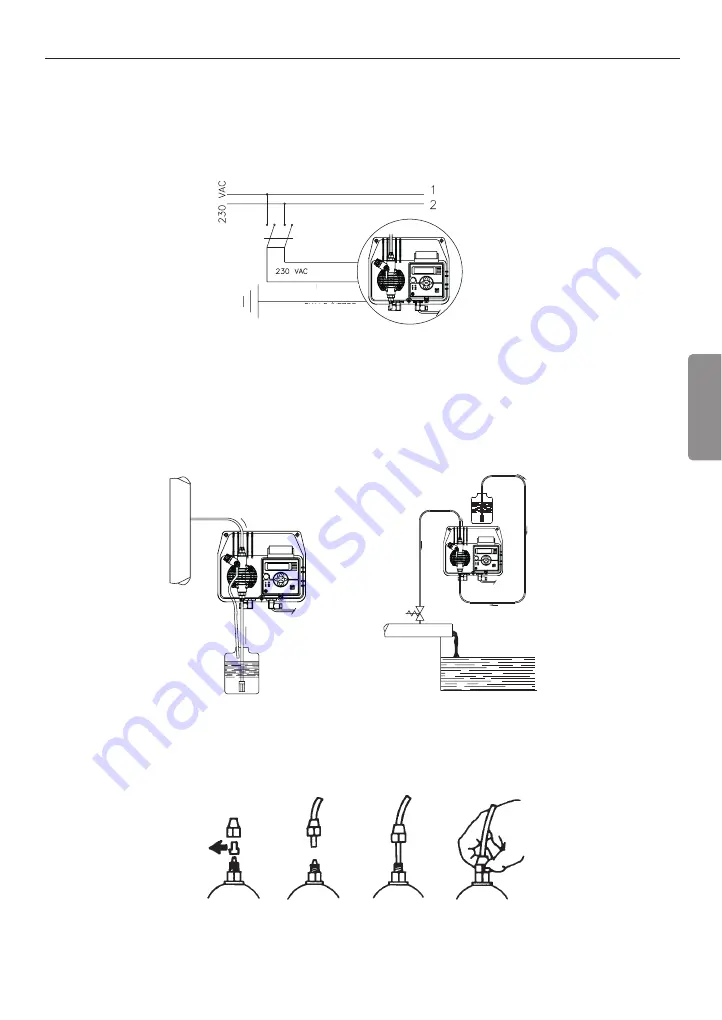
b. - Carefully observe the regulations in force in the various countries as regards electrical installations (Fig.4).

When the supply cable is devoid of a plug, the equipment should be connected to the supply mains by
means of a two-poles switch having a minimum distance of 3 mm between the contacts. Before access-
ing any of the electrical parts, make sure that all the supply circuits are open.

Fig. 4

c.-  Locate the pump as shown in fig. 5 bearing in mind that it may be installed either below or above the level

of the liquid to be dosed, though the level difference should not exceed 2 meters. When the process plant in
which the pump is installed is operating at atmospheric pressure (no back pressure) and the chemical tank
is situated above the plant (Fig. 6), the condition of the injection valve should be checked at regular inter-
vals, because excessive wear and tear could cause additive to drip into the plant even when the pump is shut
down. If the problem persist, install a properly calibrate counter-pressure valve (C) between injection point
and the valve. In the case of liquids that generate aggressive vapours, do not install the pump above the
storage tank unless the latter is hermetically sealed.

Fig. 6

d. - The discharge nipple will always remain in the upper part of the pump. The suction nipple, which serves to

attach the hose (with filter) leading into the chemical tank, will therefore always be situated in the lower part
of the pump.

Fig. 7

e. Remove the protection caps from the two nipples, slide the hoses over the connectors, pushing them right

home, and then fix them with appropriate tube nuts. (Fig. 7).

Fig. 5

C

• 

23 

ENGLISH

BLUE

BROWN

YELLOW/GREEN

Summary of Contents for BT MA/M

Page 1: ...BT BTB MA M UNI EN ISO 9001 2008 www etatronds com NORME DI INSTALLAZIONE USO E MANUTENZIONE OPERATING INSTRUCTIONS AND MAINTENANCE IT UK...

Page 2: ......

Page 3: ......

Page 4: ......

Page 5: ...ZIONE 7 4 0 MANUTENZIONE 10 5 0 NORME PER L ADDITIVAZIONE CON ACIDO SOLFORICO 10 6 0 PANNELLO COMANDI E SCHEMA DI IMPIANTO TIPICO 11 7 1 DESCRIZIONE DELLE FUNZIONI ACCESSORIE 12 8 0 INTERVENTI IN CASO...

Page 6: ...onei ed irragionevoli 1 4 RISCHI Dopo aver tolto l imballaggio assicurarsi dell integrit della pompa in caso di dubbio non utilizzare la pompa e rivolgersi a personale qualificato Gli elementi dell im...

Page 7: ...lle pompe tutti i particolari con relativa nomenclatura in modo tale da poter avere un quadro completo dei compo nenti della pompa Tali disegni sono comunque indispensabili nel caso si dovesse procede...

Page 8: ...Cassa in alluminio pressofuso protetta con PTFE BT MA o ignifuga antiacida BTB MA Pannello comandi protetto con coperchietto trasparente in policarbonato e relativa guarnizione Alimentazione elettric...

Page 9: ...n accurato dosaggio del volume di iniezione Fig 2 Corpo pompa in PVC Flussostato Fig 2 2 3 MATERIALI A CONTATTO CON L ADDITIVO 1 DIAFRAMMA PTFE 2 CORPO POMPA Polipropilene PVC 04 20 05 20 30 04 50 03...

Page 10: ...d Standard power supply Volts Hz 230 V 50 60 Hz 230 V 50 60 Hz 230 V 50 60 Hz 230 V 50 60 Hz 230 V 50 60 Hz 230 V 50 60 Hz 230 V 50 60 Hz 230 V 50 60 Hz 230 V 50 60 Hz 230 V 50 60 Hz 230 V 50 60 Hz 23...

Page 11: ...essione atmosferica additivazione a scarico libero ed il serbatoio del l additivo deve essere assolutamente posizionato pi in alto del punto di iniezione Fig 6 controllare perio dicamente la funzional...

Page 12: ...caso la pompa sia attrezzata con la valvola di spurgo mantenere la valvola di spurgo B aperta fino a quando sar fuoriuscita tutta l aria contenuta nel corpo pompa f Evitare curve inutili sia sul tubo...

Page 13: ...ingressi non utilizzati in modo che non vi siano contatti accessibili dopo l installazione della pompa dosatrice per motivi di compatibilit e sicurezza e comunque che i relativi cavi di collegamento...

Page 14: ...o ci possiamo suggerire come intervenire se la pompa lavora con ipoclorito di sodio caso pi frequen te a Assicurarsi che la stessa sia disattivata elettricamente entrambe le polarit staccando i condut...

Page 15: ...alimentazione elettrica C Filtro H Pressacavo di alimentazione I Serbatoio con additivo V Impianto 6 3 CORREDO n 1 tubo aspirazione in PVC 10x14 tipo cristal trasparente flessibile di m 2 n 1 tubo di...

Page 16: ...i impostati dall operatore IMPULSI DI RIFERIMENTO e MAX DIFFE RENZA mette la pompa in uno stato d allarme vengono bloccate le iniezioni il led n 1 fig 12 diventa rosso si accende il led giallo di alla...

Page 17: ...Centri di Assistenza DISPLAY ACCESO LED ROSSO POWER STAND BY ACCESO LA POMPA NON DA IMPULSI a Controllare la regolarit della programmazione o premere il pulsante START STOP LA POMPA DA IMPULSI IN MODO...

Page 18: ...re i parametri di funzionamento Premi il tasto Start Stop per mettere la pompa in Stand by Ora possibile modificare la portata impulsi minuto Premi il tasto F Ora possibile modificare gli impulsi di r...

Page 19: ...ossibile impostare la massima differenza di impulsi accettabili prima di emettere la segnalazione Freccia sx decrementa Freccia dx incrementa PREMI START STOP La pompa entra in funzione E possibile mo...

Page 20: ......

Page 21: ...2 3 0 INSTALLATION 23 3 1 INJECTION VALVE INSTALLATION DIAGRAM 24 4 0 MAINTENANCE 26 5 0 HOW TO OPERATE WHEN DOSING SULPHURIC ACID 26 6 0 CONTROL PANEL AND TYPICAL INSTALLATION 27 7 1 DESCRIPTION OF A...

Page 22: ...The manufactures cannot be held responsible for damage deriving from improper erroneous or unreasonable use of the pump 1 4 RISKS After unpacking the pump make sure it is completely sound In case of d...

Page 23: ...of a two poles switch with 3 mm minimum distance between the contacts Fig 4 2 Relieve all the pressure from the pump head and injection tube 3 Drain or flush all dosing liquid from the pump head This...

Page 24: ...ch regulates the flow rate from 0 to 100 OPERATING FUNCTIONS The pump can be programmed to operate manually from 0 to 100 of the flow rate 137 288 7 222 8 108 94 244 198 122 122 127 5 168 23 23 10 10...

Page 25: ...ustment system this control pro vides accurate capacity adjustment Fig 2 Pump head made of PVC Flow sensor Fig 2 2 3 LIQUID ENDS MATERIALS DIAPHRAGM PTFE PUMP HEAD Polypropylene PVC for 04 20 05 20 30...

Page 26: ...ent elettr standard Standard power supply Volts Hz 230 V 50 60 Hz 230 V 50 60 Hz 230 V 50 60 Hz 230 V 50 60 Hz 230 V 50 60 Hz 230 V 50 60 Hz 230 V 50 60 Hz 230 V 50 60 Hz 230 V 50 60 Hz 230 V 50 60 Hz...

Page 27: ...eters When the process plant in which the pump is installed is operating at atmospheric pressure no back pressure and the chemical tank is situated above the plant Fig 6 the condition of the injection...

Page 28: ...ief valve B up to all the air in the pump head will be out f Try to keep both the suction and discharge hose as straight as possible avoiding all unnecessary bends g Select the most appropriate inject...

Page 29: ...n will protect the internal circuitry from unwanted shorts and or the power surge either from the operator or from different sources There will be no accessible contacts after installation is complete...

Page 30: ...perating suggestions when dosing sodium hypochlorite most frequent case a disconnect the pins from the mains or by means of a onnipolar switch with 3 mm minimum distance between the contact b disconne...

Page 31: ...lve B Power supply C Filter H Strain Relief Bushing I Chemical tank V Process tank 6 3 ACCESSORIES 1 flexible PVC suction hose trasparent crystal type length 2m 1 semirigid polyethylene hose white len...

Page 32: ...of this alarm to be activated can be set by the user number of the missed pulses before the alarm comes on Reference pulses periodic break between a control and the following one Max count diff maxim...

Page 33: ...Y ON PUMP NOT OPERATIONAL a Check whole programming data previously inserted or push the Start Stop button PUMP PULSES ARE NOT CONSTANT a Check that supply voltage is within 10 of rated voltage FLOATI...

Page 34: ...and by mode Push the Start Stop button to put the pump in Stand by mode It is possible to modify the flow rate pulses minute Push F button It s possible to modify the reference pulses Flow sensor Alar...

Page 35: ...right arrow F It is possible to set the maximum injection difference before sounding Decreasing left arrow Increasing right arrow PUSH START STOP The pump starts working It s possible to modify the p...

Page 36: ...Serie BT MA Series 32...

Page 37: ...2711 3750 3750 3751 3751 Bxx Bxx 3753 3753 E03 E03 2711 2711 3752 3752 1718 1718 4001 4001 6201 6201 1710 1710 5402 5402 7601 7601 5231 5231 5230 5230 5215 5215 5231 5231 2704 2704 1719 1719 2704 2704...

Page 38: ...ete di raccordo Complete injection valves A 11 VALVOLA A LABBRO 20 l h 20 l h LIP VALVE 1202 1303 2812 A 12 VALVOLA A LABBRO 30 l h 50 l h 30 l h 50 l h LIP VALVE Valvole a labbro Lip valves Valvole s...

Page 39: ...on spurgo manuale Manual air bleed pump head 1201 1202 1302 Axx 8301 2501 2813 2818 3900 3907 Axx 8301 1302 1201 1202 2810 2812 1903 1703 2810 2812 Bxx 6401 6101 6501 6301 2401 1901 1801 Exx Elettroma...

Page 40: ...ATRON FRANCE 1 Mail Gay Lussac 95000 Neuville Sur Oise Tel 33 0 1 34 48 77 15 Fax 33 0 1 78 76 73 95 3 rd Mytishenskaya 16 2 129626 Moscow RUSSIA Phone 7 495 787 1459 Fax 7 495 787 1459 RUSSIAN FEDERA...

Reviews: