2020-03-12
EN0000000381V.003X.47.0
93118-002
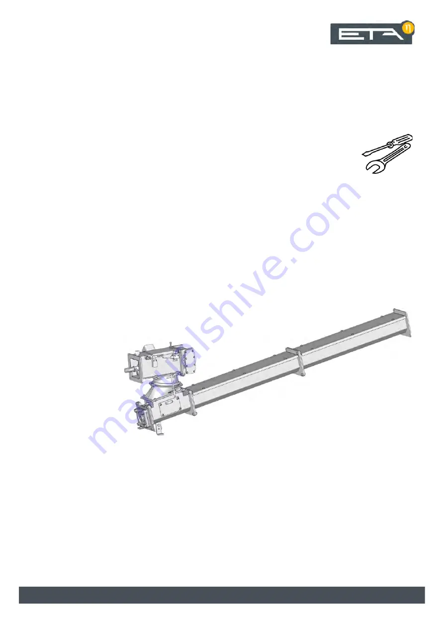
Intermediate Conveyor Screw
Operating Instructions
Page 1: ...2020 03 12 EN 0000000381 V 003 X 47 0 93118 002 Intermediate Conveyor Screw Operating Instructions...
Page 2: ...ETA Heiztechnik Gewerbepark 1 A 4716 Hofkirchen an der Trattnach Tel 43 0 7734 22 88 0 Fax 43 0 7734 22 88 22 info eta co at www eta co at...
Page 3: ...n 4 1 2 Warranty guarantee and liability 5 2 Technical data 6 3 Overview 8 4 Installation 9 5 Electrical connections 15 6 Configuration 16 6 1 Example 1 16 6 2 Example 2 17 7 Concluding activities 19...
Page 4: ...s Switch the boiler on off with the mains switch Perform a visual check of the components Clean the components with a soft cloth for example Remove deposits with a vacuum cleaner or an ash vacuum Remo...
Page 5: ...her contained in this documentation or included as a separate document Repairs Repairs are only permitted using spare parts provided by us The only exceptions are common standardised parts such as ele...
Page 6: ...6 www eta co at Technical data 2 Technical data Fig 2 1 Side view Fig 2 2 Top view...
Page 7: ...Ball joint diameter K1 mm 200 250 compatible boilers eHACK kW 20 80 100 170 180 240 HACK VR kW 250 333 350 500 Intermediate Conveyor Screw Unit BG 1 BG 2 BG 2 5 BG 3 Trough width W mm 140 190 230 Ball...
Page 8: ...e cover 3 Safety switch detects whether the maintenance cover is open or closed 4 Limit switch triggers when fuel presses against the maintenance cover from below 5 Drop chute lower part with light ba...
Page 9: ...te Only install the transmitter and receiver hand tight on the lower part of the drop chute Fig 4 3 Light barrier in lower part of drop chute There is no defined mounting side for the transmitter and...
Page 10: ...ecessary repair for example Fig 4 6 Conveyor screw Make sure that the thread is continuous Fig 4 7 Continuous thread Mount the closed trough on the lower part of the drop chute Fig 4 8 Closed trough A...
Page 11: ...the conveyor screw with Stauffer grease and connect them Make sure that the thread is continuous Fig 4 11 Start screw Install the drop chute on the trough Fig 4 12 Drop chute Attach a seal to the fla...
Page 12: ...the conveyor screw with Stauffer grease and connect them Make sure that the winding is continuous Fig 4 15 Start screw Install the drop chute on the trough Fig 4 16 Drop chute Attach a seal to the fl...
Page 13: ...n the ground for later attachment Fig 4 18 Support stands Installing the discharge drive Align the screw conveyor with the drive using the feather key Fig 4 19 Drive Slide the drive onto the screw con...
Page 14: ...ing the support stands on the floor Fix the support stands to the floor with suitable screws Fig 4 23 Support stands The support stands can be extended by the customer The lower part of the drop chute...
Page 15: ...e Before beginning any work isolate the system completely from all power sources ensure that it cannot be switched back on and verify that it is safely isolated from supply CAUTION Flexible stranded c...
Page 16: ...diate conveyor screw Configuration Circuit board Function blocks Description HA C 0 Boiler Wood chip boiler Settings Fuel Set the used fuel type Conveyor type Special conveyor To regulate the special...
Page 17: ...screw mounted on the stoker is controlled by the boiler Circuit board Function blocks Description HE C 0 Special conveyor Intermediate conveyor screw between agi tator and intermediate conveyor screw...
Page 18: ...ngs Motor rated output See drive type plate Options Light barrier in drop chute The light barrier is included in the delivery scope Circuit board Function blocks Description Connections Producers Cons...
Page 19: ...and outputs menu Select the stoker unit Stoker unit and press the button for manual operation Only start the discharge drive with the Fwd button Fig 7 2 Menu for manual operation Check the direction...
Page 20: ...the discharge does not convey any fuel or if the control indicates the light barrier dirty error the light barrier in the drop chute must be checked and cleaned Remove the maintenance cover to reach t...
Page 21: ...Rectifying problems 21 Replace the maintenance cover Tighten the nuts alternately and evenly Switch on the boiler at the mains switch...
Page 22: ...22 www eta co at Circuit diagram 9 Circuit diagram...
Page 23: ...cke_ HE C_am_Kessel _EN Datum Name Norm Urspr Ers f Ers d Ersteller Auftrags Artikel Nr Zeichnungs Pfad Blatt Gepr Bearb Datum Kommision 93978 002 30 09 2019 29 07 2014 wip 1 5HJHOXQJ DQGNlVWHQ ZLVFKH...
Page 24: ...r Auftrags Artikel Nr Zeichnungs Pfad Blatt Gepr Bearb Datum Kommision 93978 002 30 09 2019 29 07 2014 wip 1 5HJHOXQJ DQGNlVWHQ ZLVFKHQVFKQHFNH RVLHUVFKQHFNH Boiler Dateiname bQGHUXQJ Version 1 5 DI 1...
Page 25: ...Q ZDOO KRXVLQJ 7 WRXFK ZLVFKHQ RVLHUVFKQHFNHB BLPB DQGJHKlXVH B 1 DWXP 1DPH 1RUP 8UVSU UV I UV G UVWHOOHU XIWUDJV UWLNHO 1U HLFKQXQJV 3IDG ODWW HSU HDUE DWXP RPPLVLRQ HQG 1 5HJHOXQJ DQGNlVWHQ ZLVFKHQV...
Page 26: ...6 UWLNHO 1U 6 UWLNHO 1U RQYH RU N RLOHU IURP N 2Q WKH HOHFWURQLFV SDQHO DW WKH ERWWRP ULJKW LIIHUHQW ERLOHU YDULDQWV ZLVFKHQ RVLHUVFKQHFNHB BLPB DQGJHKlXVH B 1 DWXP 1DPH 1RUP 8UVSU UV I UV G UVWHOOHU...
Page 27: ......
Page 28: ...www eta co at www eta co at downloads DOWNLOAD...