background image

Pellet store

Requirements for pellet store

35

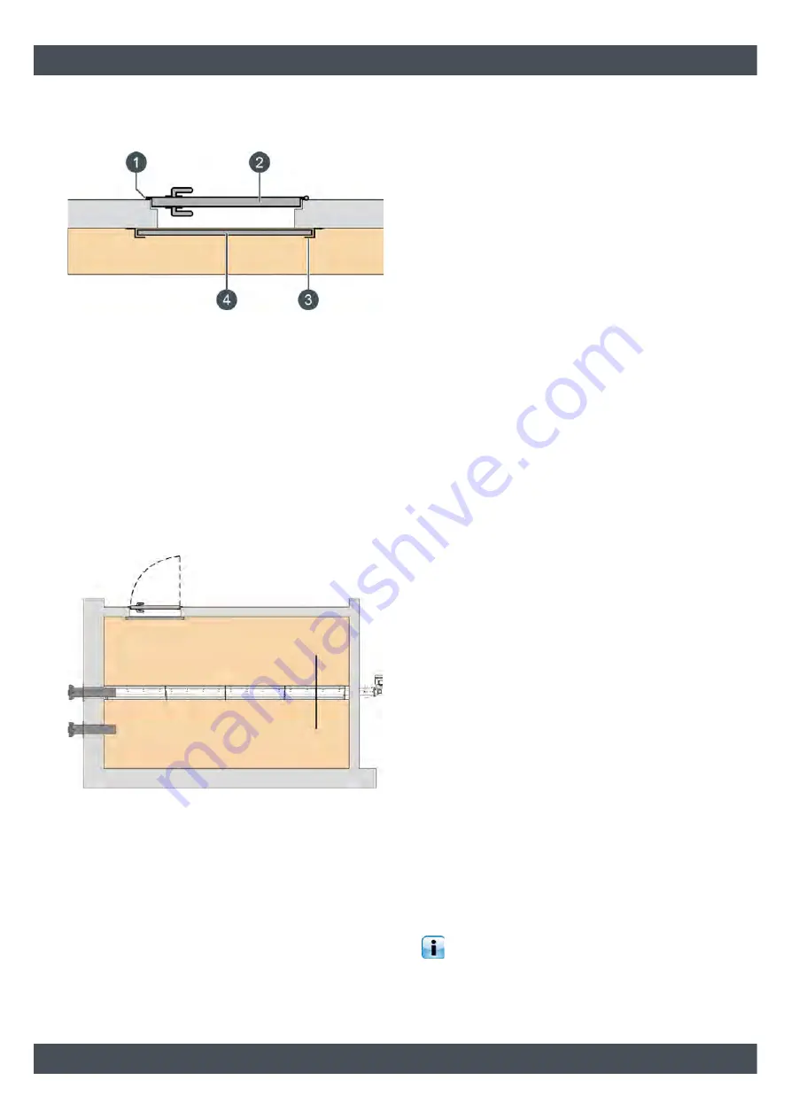
boards  must  be  mounted  on  the  inner  wall  (30 mm
thick  with  tongue  and  groove)  so  the  pellets  cannot
push against the door, or so that it can be opened.

1

Seal between door and frame

2

Fire-resistant door

3

Z profile for boards

4

Boards

The  door's  lock  must  be  sealed  against  dust  on  the
inner side. In spite of a widely circulated construction
document, the door handle on the inner side may not
be removed. It must be possible to open the door from
the inside in an emergency.
For screw conveyors, the store room door should be
positioned  on  the  opposite  side  to  the  screw  drive.
Because  this  area  of  the  store  empties  first  and,  if
required, facilitates quick access to the store.

Electrical socket for pellet supplier's blower

For  the  pellet  supplier's  suction  blower,  a  230 V
electrical socket (C-13A fuse) in the vicinity of the filling
nozzle is useful.

6.2

Requirements for pellet store

Structural requirements

The pellet store's walls must withstand the load caused
by  the  weight  of  the  pellets  (bulk  weight  650  kg/m³).
The plasterwork should also be durable enough that it
cannot rub or flake off and contaminate the pellets.
If  the  forces  from  the  tilted  floor  construction  are
directed  into  the  floor  and  not  the  wall,  then  the
following  wall  thicknesses  have  proven  effective  in
practice  given  proper  anchoring  in  the  enclosing
masonry:

Concrete 100 mm thick.

Common  brick  170 mm  thick  and  plastered  on
both sides.

Post-and-beam  walls  with  120  mm  beams,
clearance 625 mm,  with  wooden  panelling  15-
20 mm thick on both sides.

Dry storage for pellets

Pellets  are  very  hygroscopic;  they  absorb  moisture
from the environment. On contact with water or moist
walls,  they  swell  up  and  break  apart,  becoming
unusable.
The pellet store must stay dry throughout the year. The
normal  humidity  encountered  in  normal  residential
construction throughout the year is not harmful to the
pellets.
If there  is  a  danger  of moist  walls  from time to  time,
such  as  in  older  buildings,  we  recommend  installing
rear-ventilated wood facing on the walls or storing the
pellets in a fabric silo.

Regularly remove the dust from the pellet store

The  pellet  store  must be regularly  "emptied",  so  that
the  dust  can  be  removed  from  the  pellet  store.
Because  the  pellets  "crumble"  after  a  few  years  and
produce dust. In combination with increased air humid-
ity,  this  dust  can  lead  to  blockages  of  the  suction
probes  or  prevent  the  pellets  from  sliding  on  the
slanted floor in the storeroom.
An increased amount of dust often occurs in oversized
storerooms  that  are  only  filled  every  2  -  3 years,
because  the  high  bulk  weight  of  the  pellets  slowly
crushes  the  pellets  below.  Even  in  storerooms  with
suction probes without inclined floor, "old" pellets often
remain between the suction probes and then crumble
slowly.

Therefore, the pellet store must be "emptied" at
the latest every three years, so that the dust can

be removed before refilling. Shovel "old" pellets either
to  the  discharge  screw  or  the  suction  probe,  so  that
they are quickly used up.

Summary of Contents for 11120L

Page 1: ...2020 07 21 EN 0000000371 V 012 2503 939023 004 TWIN pellet burner 40 50 kW Installation...

Page 2: ...ETA Heiztechnik Gewerbepark 1 A 4716 Hofkirchen an der Trattnach Tel 43 0 7734 22 88 0 Fax 43 0 7734 22 88 22 info eta co at www eta co at...

Page 3: ...pellet burner 21 4 5 Attaching pellet hoses 25 4 6 Network connection 26 5 Electrical connections 28 5 1 Requirements 28 5 2 Circuit board PE C4 Twin 30 5 3 Connection between SH and TWIN 32 5 4 Conc...

Page 4: ...ion of the LAN cable see 4 6 Network connection Extended warranty We grant an extended warranty if the product is com missioned by an authorised partner company or by our own customer service In this...

Page 5: ...stem must be repaired at once Minimum return temperature 60 C Ensure a minimum return temperature of 60 C to the boiler Install safety valve and thermal relief valve A safety valve triggered at 3 bar...

Page 6: ...temperature limiters safety valves and thermal discharge valves 1 4 Dismantling disposal Dismantling Before dismantling Stop heating Switch off the boiler with the mains switch and ensure that it can...

Page 7: ...General Dismantling disposal 7...

Page 8: ...or installation on the right or left side The illustration shows a log boiler 40 60 kW with the pellet burner on the left side 1 Safety heat exchanger R1 2 external threads 2 Discharge with R1 2 coupl...

Page 9: ...t in dry flue gas at partial full load 10 12 10 12 8 Exhaust temperature of pellet burner at partial full load C 110 170 Required flue draught Pa 5 Pa a draught limiter is required above 30 Pa Carbon...

Page 10: ...of the package system 5 Factor II evaluation of primary solid fuel boiler and ad ditional heater 0 Value for III 294 11 Pr 1 34 0 92 0 84 0 67 0 54 Value for IV 115 11 Pr 0 52 0 36 0 33 0 26 0 21 Con...

Page 11: ...at partial load 79 2 81 4 81 3 81 3 81 2 Electrical power consumption at maximum load kW 0 061 0 102 0 116 0 116 0 116 Electrical power consumption at partial load kW 0 046 0 057 0 066 0 066 0 067 Ele...

Page 12: ...2012 Heating boilers Part 5 Heating boilers for solid fuels manually and automatically stoked nominal heat output of up to 500 kW Terminology requirements testing and marking EN ISO 12100 2011 Safety...

Page 13: ...ght side Check space requirement The pellet burner is available for installation on the left or right side of the log boiler If the log boiler is already installed the space required by the pellet bur...

Page 14: ...ver Fig 4 4 Heat exchanger cover Remove the cleaning lever To do so remove the bolt and pull out the lever Fig 4 5 Cleaning lever Removing the cover from the top Remove cover over the door frame Fig 4...

Page 15: ...tuators must be located on the side of the log boiler on which the pellet burner is not installed If the actuators are located on the same side the pellet burner will be installed the mounting side of...

Page 16: ...nt both twist guards on the opposite side in the brackets Fig 4 13 Twist guards Remove insulation The required cut out for the pellet burner cleaner is precut into the boiler insulation Trim it with a...

Page 17: ...ber is already pre milled Strike through the visible lining in the opening with a hammer shaft Fig 4 18 Refractory lining Remove the piece of lining that has been broken off from the combustion chambe...

Page 18: ...he bracket and both pins Fig 4 22 Installation on the left side of the boiler Manually turn the connecting rod to check its free movement For a complete revolution of the connecting rod the cam must a...

Page 19: ...the sensor in the bracket The position depends on the mounting side of the heat exchanger cleaning See the following figures for this Fig 4 26 Sensor position mounting on the left side of the boiler F...

Page 20: ...t terminal S514 Fig 4 29 Connect the drive and sensor Closing the heat exchanger cover Re attach the heat exchanger cover Turn the ball knob up to the stop to suspend the heat exchanger cover Then tig...

Page 21: ...tuator with the nut For the lower actuator ad ditionally push on the spring removed from the opposite side as well as the supplied bushing and secure with the nut Fig 4 34 Spring and bushing Do not ov...

Page 22: ...4 36 Pellet burner Manually attach the pellet burner on both sides with an M8 long nut each Fig 4 37 Long nut Using a spirit level and the levelling screw adjust the pellet burner so it is level on t...

Page 23: ...stening bracket Mount the cover for the bottom of the pellet burner Fig 4 41 Cover Mount the fastening bracket on the top side Fig 4 42 Fastening bracket Mount the fastening bracket for the outside of...

Page 24: ...same distance to the pellet nozzles Fig 4 46 Panel If an adjustment of the clearance is required the position of the pellet hopper must be altered slightly To do this loosen both screws on the pellet...

Page 25: ...protection sleeves must be fitted over both pellet hoses In wall ducts a fire protection sleeve must be mounted on each side with ceiling ducts only positioned on the ceiling side Fig 4 52 Fire protec...

Page 26: ...le next to the connections Fig 4 54 Connections for pellet hoses Mounting the pellet hoses on the discharge On the ends of both pellet hoses free around 5 cm of the copper wire strands from the hoses...

Page 27: ...Installation Network connection 27...

Page 28: ...ed DANGER Electric shock There are live parts on the circuit boards If touched they can cause injury and property damage Before beginning any work isolate the system completely from all power sources...

Page 29: ...ections Requirements 29 Fig 5 3 Speed controlled pump Fig 5 4 Special function pump with supply extension 230 V Fig 5 5 Special function changeover valve with three point controlling Fig 5 6 Special f...

Page 30: ...inimum cross sec tion Default assignment S20 230 V supply from circuit board SH C terminal S82 S25 230 V input from circuit board SH C terminal S82 S28 230 V input 3 x 1 mm Emergency stop switch S29 2...

Page 31: ...V output Vacuum turbine S30 STB 230 V input Wire bridge S30 ASCHENK BEL 230 V input Ash box switch S30 ROST 230 V input switch de ashing and grate S30 GLUTBETT 230 V input switch firebed S32 230 V out...

Page 32: ...trical connections 5 3 Connection between SH and TWIN Fig 5 7 Connection between SH and TWIN 5 4 Concluding activities Installing the panels Reattach the panels over the boiler circuit boards Fig 5 8...

Page 33: ...Fig 5 10 Panel on the top Mount the cover over the automatic heat exchanger cleaning Fig 5 11 Cover Removing protective film Remove protective film from all covers After longer periods of operation o...

Page 34: ...s prevents air circulation from the lower boiler to the pellet store Testing before initial fill up Before filling the pellet store test the functionality of the entire heating system and the pellet c...

Page 35: ...170 mm thick and plastered on both sides Post and beam walls with 120 mm beams clearance 625 mm with wooden panelling 15 20 mm thick on both sides Dry storage for pellets Pellets are very hygroscopic...

Page 36: ...toreroom Example Room width 2 m and height 2 4 m The table shows a usable cross section of 3 m The volume of pellets to be stored in the example above is 7 2 m 7 2 m 3 m 2 4 m minimum room length A co...

Page 37: ...n nozzle so that the pellet supplier recognises which nozzle the pellets are blown into Opposite the middle filling nozzle an impact protection mat is installed 500 mm from the wall to prevent damage...

Page 38: ...0 mm under the ceiling of the pellet store so that the pellets are not blown against the ceiling To install the filling nozzles in smooth holes or sewer pipe cut outs so they cannot twist the ETA fill...

Page 39: ...ength pose no problem Height differences of one floor or even two for short lines can also be overcome without problems Extension with aluminium piping only Only aluminium piping may be used for the f...

Page 40: ...This applies for systems with conveyor screws as well as for suction heads Construction of tilted floor for storeroom For the slanted floor three ply concrete formwork panels 27 mm thick have proven...

Page 41: ...and fasten it to the floor Fig 6 11 Suction probe on a wooden board Pad wall opening for conveyor screw trough Sound from the screw can be transmitted through the pellet store walls into the house To...

Page 42: ...out Fig 6 14 Note bending radius Fig 6 15 Avoid twisting pellet hoses Fig 6 16 Use pipe guides or pipe supports Single piece suction hose The suction hose for the pellets must always consist of a sin...

Page 43: ...in Austria Legally fire safety is regulated in the various building codes of the states though all state legislation is based on the TRVB H 118 Technische Richtlinien vorbeu gender Brandschutz automat...

Page 44: ...s and doors and no usage restrictions are stipulated Pellet stores over 10 000 litres 6 5 tons Walls and ceilings REI90 F90 no lines through walls No other use Doors self closing and fire resistant EI...

Page 45: ...venti lation line Store size 10 tonnes Store size 10 tonnes 2 m Ventilation via sealing cover with the follow ing requirements Two ventilated sealing caps on two Storz A couplings Ventilation to the...

Page 46: ...unventilated sealing cover 2 Ventilation opening outside Even if the filling nozzles protrude into a room in which ventilation is available NORM M 7137 recommends using only sealed unventilated sealin...

Page 47: ......

Page 48: ...www eta co at www eta co at downloads DOWNLOAD...

Reviews: