


9
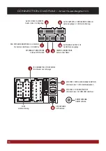
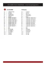
CONNECTION DIAGRAM / Anschlussdiagramm
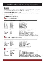
Camera connections G71-CCD0037
Name
Connector/Color
Function
CCD-CVBS-IN
RCA yellow
Video signal input from the rear camera
FRONT-CCD-IN
RCA yellow
Video signal input from the front camera
REVERSE IN
blue
Reverse gear signal input. Please don‘t use when vehicle‘s CANBUS is operated.
If CAN signal is not present, the reverse signal (12V, for example the reversing
light) can be connected here. The ESX device switches to the „CCD CVBS IN“
input as soon as „REVERSE IN“ is supplied with 12V and „CCD-Camera“
checkbox in the option menu under „DISPLAY“ is activated.
CCD-POWER OUT
yellow
12V power supply output for an aftermarket rear view camera with max.
100mA. 12V will be supplied, as soon as „REVERSE-IN“ is supplied with 12V.
FRONT CCD-POWER OUT red
12V power supply output for an aftermarket rear view camera with max.
500mA. 12V will be supplied, as soon as the ESX device is turned on.
Make sure that your camera is suitable for continuous operation.
GND
black
Ground terminal of the power supply of an optional camera (front and rear).
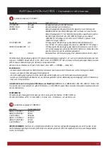
Connect the reverse signal (12V when reverse gear is engaged, for example, also by reversing light) of the vehicle to „REVERSE“ (blue
cable). The „GND“ and „CCD POWER OUT“ cables must not be connected mandatory, but can be used as a power supply for the camera.
Now activate the „CCD-Camera“ checkbox under APPS -> OPTIONS -> DISPLAY at the ESX device.
Operation note:
- Special feature: Push the right rotary controller to display the rear view cam, even when the reverse gear is not engaged.
- When the reverse gear is engaged, the device does not allow any other operation, all the buttons and controllers except
volume controller are blocked for security reasons. If the device is switched off and the reverse gear is engaged, the device
does not even turn on.
Installation note with original OEM camera for type 290 Model:
If the CANBUS cable set „VNA-DUC-CAN-SET“ (See page 3) is used,
only the yellow RCA plug „CCD CVBS IN“ must be connected. All other signals are taken over by the CANBUS.
FRONT VIEW CAMERA
Connect the camera via RCA to the yellow RCA connector „FRONT CCD IN“.
Switch to „Camera“ or „Front Camera“ in the menu „AV/TV“ to display your camera view.
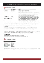
Audio/Video Outputs G71-MNV0009
Name
Connector/Color
AUDIO L OUT/ZONE-1
RCA white
AUDIO R OUT/ZONE-1
RCA red
V-OUT1/ZONE-1
RCA yellow
AUDIO L OUT/ZONE-2
RCA white
AUDIO R OUT/ZONE-2
RCA red
V-OUT2/ZONE-2
RCA yellow
IMPORTANT NOTE:
Connection for e.g. headrest monitors or other devices such like TVs in the rear. The audio/video outputs is always
the same signal to which will be played just on the ESX device. An independent input source selection is not possible.
9
10


