Esu LokProgrammer v 4.0 Instruction Manual Download Page 17

Change Decoder Settings


Functions / Identification / CVs 


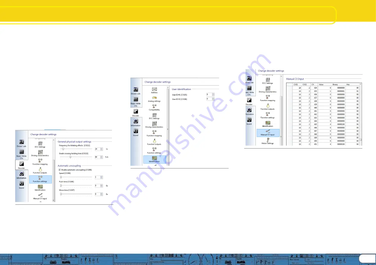
8.6.6 Function settings, “General” and “Automatic uncoupling” 
 
As mentioned  in 8.6.5 above, when mapping logical 
functions to a function key, in some cases you should also 
use Function settings in order to enable the response you 
desire when the function key is engaged.  General settings 
are for configuring lighting effects, and allow you to set the 
blink frequency for lighting situations that require blinking 
lights (CV112), and for setting grade crossing holding time 
(CV132).  Holding time is the amount of time the grade 
crossing effect  is enabled. 
 
Automatic uncoupling is where automatic uncoupling is 
enabled (CV246), and where you can set the uncoupling 
speed across a range of 1 

– 255 (same as the speed table 

range), default is 1 (CV246).  Push time (CV248) is the time 
in seconds the automatic push is in effect; and Move time 
(CV247) is the time in seconds the locomotive moves away 
from the uncoupled car(s).  Of course “time” relates directly to 
distance traveled at the speed set for the duration of the 
automatic uncoupling cycle.  See figure 37. 


                      Fig. 37.: Configure Function settings


8.7. Identification


8

.7.1 Data fields, “User identification” 

The user identification fields are open fields that can be used for any 
purpose.   These are designated as “User ID #1” and “User ID #2”.  
CV’s are CV105 and CV106 respectively.  Value range for both is 0 – 
255 and they can be set individ

ually or together.  Setting these CV’s 

does not change any decoder behavior, they are an open code 
section and can be used for any purpose, perhaps to track a certain 
version, or function key structure.  Default value is 0 for both CV’s.  
See figure 38 


              Fig. 38.: User Identification 


8.8. Manual CV Input


8.8.1 Manual CV Input 

This section of the change decoder data screens is made available 
should you wish to make manual CV changes without using the 
preformatted decoder set up screens and views.  It is also very useful 
for researching CV’s.    When you export the decoder CV listing (See 
“5.3 Tools”, Export CV list) the text file that is created during the export 
will consist of the same data displayed in this view. 
 

8.8.2 CV changes 

CV changes can be made directly by overwriting the data in any of 
the data fields; “Value”, “Binary”, or “Hex”, simply enter the value you 
wish and then tab out of the field and the data will be changed and the 
other two data columns will update.  Of course it is much easier to 
enter direct numeric data in the “Value” column than it is to write 
Binary or Hex data.   


After you are finished making changes, the new values may be 
written to the decoder using “Write decoder data”  (See “5.2 
Programmer

”, Figure 12)   

 
Note: The ability to make manual changes is very powerful and 
should be used with care.  Consider saving the changed project 
file under a new name in order to provide a way to rewrite last 
known good data to the decoder to recover from mistakes.  See 
figure 39.  


                                                            Fig. 39.: Manual CV Input


8.9. Motor Settings


Here is where you configure speed table, load control, PWM 
frequency, and overload protection settings on the v4 decoder 
series.   Information presented here deals directly with making 
desired settings using the LokProgrammer tool to configure the 
decoder, therefore the level of detail presented is not at the same 
level as is found in the v4 decoder manual.  Please use the 
detailed information found in the decoder manual, chapter 10, as 
the preferred source for decoder information. 
 

8.9.1 Speed table selection and configuration


(CV 2, CV 

5, CV 6, CV 26, and CV 67-97) 

 
Here you may select either a 3 point speed table (figure 40) or a 
custom speed curve (figure 41).  If you use the 3 point table you 
should set minimum and maximum speed (CV2 and CV5) and 
then pick the mid range speed (CV 6) as desired.  You may also 
use the slider on the right hand side to set both maximum and 
mid range speeds.  In order to avoid possible rough or unusual 
running, please ensure 


 17

Summary of Contents for LokProgrammer v 4.0

Page 1: ...LokProgrammer v4 0 Instruction manual For software versions 4 4 13 and on Article no Unofficial See About this manual pg 42 September 2014 1...

Page 2: ...n about LokSound decoders 7 4 Purpose of the LokProgrammer software 8 4 1 Overview 8 4 2 Assistant 8 5 Main screen 9 5 1 View Panes 9 5 2 Task bar 9 2 5 3 Tools 9 6 Driver s cab 11 7 Decoder Informati...

Page 3: ...in the appropriate manner you help to avoid negative impact on the environment and health that could be caused by inappropriate disposal Recycling of materials contributes to conserve our natural envi...

Page 4: ...ely the USB adapter cable provided to connect the LokProgrammer to any available COM port or USB port of your PC Which port you select is immaterial Please make sure that the programming track is comp...

Page 5: ...dy have experience with digital systems and also be familiar with locomotive sounds you may skip this chapter and continue reading on page 16 3 1 Sound characteristics of locomotives With LokProgramme...

Page 6: ...be heard in many a diesel locomotive with manual transmission With the LokProgrammer software you can either store the original sound of gear shifting or you may choose the option gear shift User Soun...

Page 7: ...ogramming any sounds For instance is it not possible to store any M4 project files on a DCC decoder let alone to replay them 3 5 CVs 3 5 1 Definition and application CV stands for Configuration Variab...

Page 8: ...ate facility Whenever a new version with extended functionality and bug fixing is available it will be placed in the download section on our website The appearance on the screen may change subject to...

Page 9: ...lace the locomotive on the programming track and make sure the programming track is correctly connected Then click Read decoder data in the task bar at the top of the screen The program starts to read...

Page 10: ...l and provides a starting point for setting up your model See fig 16 at top of next column 10 Fig 16 Load Control sub dialog Tools Update decoder firmware Commands an activity that will either confirm...

Page 11: ...the field Activate Cab Control the speed of the locomotive with the slide throttle Clicking into the appropriate fields turns functions on and off Up to function F12 you may also press the numbers on...

Page 12: ...propriate slide control you can adapt the start voltage and the maximum speed separately for AC or DC Analogue mode to match the characteristics of your motor or transformer Furthermore you can select...

Page 13: ...you to set values for coasting Higher Momentum settings also allow certain sound features to operate realistically such as coasting sounds and acceleration sounds 8 5 2 Allowed brake sections CV27 CV...

Page 14: ...e the screen display depends on decoder type Shown here is the display for V4 standard and micro decoders A great deal of information is available in the v4 decoder manual concerning function mapping...

Page 15: ...s the lighting button while we count the remaining buttons from F1 upwards See figure 29 next column for an example of configuring the Physical output for F0 to enable the rear light to come on when t...

Page 16: ...edwhen enabled Fade outsound when enabledfades thesoundtothe volumesettingfor Fadesound CV133 inthe soundsettings section allows simulating goingintotunnels buildings etc Diesel notchup fordiesel elec...

Page 17: ...vailable should youwishtomakemanual CVchanges without usingthe preformatteddecoderset upscreens and views It is alsovery useful for researching CV s Whenyou export thedecoderCV listing See 5 3Tools Ex...

Page 18: ...des important informationtothe decoderonhowmuchinertiathemotorhas Motors withlarge flywheels naturally havemoreinertiathansmallerones orcorelessmotors Adjust parameterI if thelocomotivejerkssomewhat j...

Page 19: ...on 8 6fordetail Fig 44 Smoke Unit set up 8 10 1 ESU Smoke unit CV s 140 138 139 Here youcanset variables tocontrol ESU andothersmoke units You canset time of operationuntilsmokeunit power off across a...

Page 20: ...ound of anarticulatedsteam engine suchas a2 8 8 0orsimilar youcancheck theboxto enablesecondarytrigger and put avalue inwiththeslider bartoset acycletimeforthesound of thedriversrunningslightlyout of...

Reviews: