


14
Change Decoder Settings
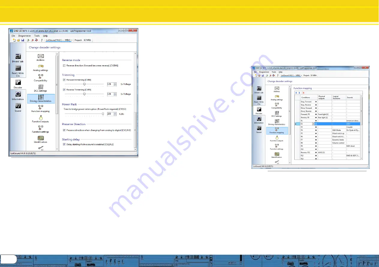
Driving Characteristics / Functions
Fig. 26.: The „Driving characteristics“ register
8.5.4. Reverse mode (CV 29)
A tick at „Reverse mode“ changes the direction of travel
and the directional characteristics of the headlights. This is
useful in case the wiring has been done incorrectly
(swapping of track
leads or motor leads).
8.5.6 Trimming (CV66, CV95)
The trim function allows you to set the maximum speed
separately for forward and reverse movement. The factor
that is used to multiply the motor voltage, results from
dividing the CV-value by 128 (forward CV 66 and reverse
CV 95).
8.5.7 Power Pack (CV 113)
V4 decoders (HO and N) provide for the installation of capacitors
or power packs (so called “keep alive” devices). CV113 allows
control of the amount of time the device is active. Setting range is
0 to 255 via the adjustment slider; an estimated active time is
shown to the right of the setting in seconds. Information for
installing capacitors or power packs can be found in the decoder
manual chapters 10.9 (configuring) and 6.11 (wiring).
8.5.8 Preserve Direction (CV124.0)
Checking this option keeps the direction constant when the v4
equipped loco transitions from DCC control to Analog controlled
track sections.
8.5.9 Starting delay (CV124.2)
Usually, when the LokSound V4.0 sound is idling and you turn up
the throttle, the locomotive begins to move only after the Diesel
engine has reached notch 1. A steam loco will even release its
brakes first and fill the cylinders. Although this behavior is very
prototypical, one might not like it because it causes some delay.
You can control this startup delay by simply not checking this
option. This will cause the LokSound V4.0 decoder to immediately
start moving when the throttle is turned up. However, the start up
sound will not be synchronized with the motion anymore.
8.6. Function views
Both LokSound V4.0 and LokSound micro V4.0 decoders have
identical function mapping. M4 and XL decoders have different
screen displays. The display will shift when the decoder type for
any given project is changed; therefore, the screen display
depends on decoder type. Shown here is the display for V4
standard and micro decoders. A great deal of information is
available in the v4 decoder manual concerning function mapping.
Of course, which sound is assigned to which sound slot may vary
depending on the decoder project. You will find a list with all
available project files “Download/Sound files/LokSoundV4.0/“ on
our home page at www.esu.eu. You may also view and print a list
with all functions and the sound slots employed.
The LokSound V4.0 decoder offers powerful and flexible function
mapping options:. Each function button can switch as many
outputs as desired. Each output can be activated by several
function buttons. Function buttons can be linked (e.g.: F3 AND F5
pressed simultaneously)
Function buttons can be inverted (e.g.: NOT when F8 is on).
Besides the buttons F0 to F28 you can also incorporate the
direction of travel or the speed (locomotive is moving / has
stopped)
You may connect as many as 5 external sensors. While
many model train enthusiasts need precisely these functions
for optimal running of all their locomotives setting up
function mapping represents so to speak the “free style”
version of decoder programming. Take your time to
understand the concept behind it before you start changing
any settings. For a complete review of all function mapping
CV’s, see the v4 decoder manual.
HINT: Even if you do not have LokProgrammer hardware,
you can still use the software as an aid in making mapping
changes in conjunction
with the “Show changed CV’s”
capability.
Fig. 27.: The „Function mapping“ register
The function mapping view is arranged as a matrix with
vertical columns for conditions, physical outputs, logical
functions and sounds. Horizontal rows list each condition
and function key for use in mapping as desired. See figure
27.
8.6.1 Function mapping,
“Conditions”
The input block (conditions block) shows which condition is
required to achieve a certain output. Conditions are for
instance “F3 On” or “Locomotive is stationary with direction
set to forward, and F8 is switched on”. Configuring the
outputs to behave as desired begins by deciding which
function or function key you wish to configure to enable an
output that will perform the desired action when the function
is on, or off.


