background image

Operation manual for M RS 420 ESTYMA control unit 

6


SAFETY PRECAUTIONS 


Warning 

– risk of electric shock. 


Before  assembly  or  disassembly  of  the  unit,  disconnect  the  power  supply  in  the 

switchgear. 


Read this operation manual carefully and thoroughly before using the unit. 


Keep  this  operation  manual  and  refer  to  it  whenever  you  work  with  this  unit  in  the 
future. 


Apply all the rules and heed all the warnings included in the unit operation manual. 


Make sure that the unit is not damaged. In case of any doubts, do not use the unit and 

contact the supplier. 


In case of any doubts concerning the safe operation of the unit, contact the supplier. 


Pay special attention to all warning signs on the unit casing and its package. 


Use the unit as intended. 


The unit is not a toy. Do not allow children to play with it. 


Under  no  circumstances  children  should  be  allowed  to  play  with  any  parts  of  the 

package of the unit. 


Access  to  small  parts  such  as  clamping  screws  or  bolts  should  be  secured  against 

children. Such elements may be delivered with the unit and may result in choking when 

swallowed by a child. 


Do not make any mechanical or electrical changes to the unit. Such changes may cause 

the unit to malfunction and fail to meet the relevant standards, leading to an adverse 

impact on the performance of the unit. 


Do not insert any objects into the unit through openings (e.g. ventilation grills), as this 

may cause short circuiting, electric shock, fire or damage to the unit. 


Do  not  allow  water,  humidity  or  dust  to  enter  the  unit,  as  this  may  cause  short 

circuiting, electric shock, fire or damage to the unit. 


Provide adequate ventilation of the unit, do not cover or block the ventilation grills, and 

ensure that there is free flow of air around the unit. 


The unit should be installed indoors unless it is adapted for outdoor operation. 


Do not expose the unit to mechanical impacts and vibrations. 


When  connecting  the  unit  to  power  supply,  make  sure  that  the  parameters  of  the 

supply network are within the unit’s operating range. 


In  order  to  avoid    the  risk  of  electric  shock,  connect  the  unit  to  a  socket  with  an 

earthing pin. The socket must be properly earthed by a licensed electrician. 


When  connecting  the  unit,  make  sure  that  it  does  not  overload  the  electrical  circuit. 

Avoid connecting the unit to one circuit with motors and other equipment that causes 
impulse interference (e.g. washing machines, fridges,  ...) 


It  is  absolutely  necessary  to  cut  off  power  supply  before  connecting  any  cables  or 

peripherals to the unit. 


Remove the plug from the socket in order to completely de-energize the unit, especially 

if you do not intend to use the unit for a longer period of time. 


Protect the power lead against damage; it should be laid in a way that ensures that 

nobody treads on it; no objects should stand on the power lead. 


All  electrical  connections  must  be  as  shown  in  the  electrical  assembly  drawings  and 

must comply with national and/or local regulations concerning electrical connections. 

Summary of Contents for Control M RS 420

Page 1: ......

Page 2: ...IGATION 10 BOILER OPERATION MODES 12 WEATHER COMPENSATED MODE WITH MIXER ACTUATOR CONTROL 12 MANUAL MODE 12 SUMMER MODE 13 BOILER TEMPERATURE SETTING 13 CONTROL OF THE FOUR WAY MIXING VALVE 14 HEATING...

Page 3: ...of the air supplied to the combustion process Thanks to solid state relays SSRs the blower has variable speed control and the reliability of the unit controlling the feeder motor has been greatly incr...

Page 4: ...between the unit and the user and the interface is very easy to use A new intuitive menu in several languages Polish English German French Lithuanian Russian A Lambda sensor ensures optimum supply of...

Page 5: ...Operation manual for M RS 420 ESTYMA control unit 5 Figure 1 Flowchart of the control unit operation...

Page 6: ...this may cause short circuiting electric shock fire or damage to the unit Do not allow water humidity or dust to enter the unit as this may cause short circuiting electric shock fire or damage to the...

Page 7: ...lead must be replaced by a maintenance service provider with a new one having the same parameters as the original lead DISPOSAL OF OLD EQUIPMENT This electronic equipment is made of materials which ar...

Page 8: ...cal connections LOCATION The unit is intended for indoor installation only After selecting the location make sure that it meets the following requirements The location must be free from excessive humi...

Page 9: ...ee the contact details on the last page of this manual ROOM TEMPEATURE REGULATOR The M RS ESTYMA controller can work with any temperature room regulator with closing contacts The room regulator should...

Page 10: ...is shown in Figure 2 submenus are used to display and change operation parameters In order to change a parameter press ENTER The parameter changed is displayed in cycles In order to edit the parameter...

Page 11: ...Operation manual for M RS 420 ESTYMA control unit 11 Figure 4 MENU...

Page 12: ...rogrammable heating curve so there is no need to change the boiler temperature manually when the outdoor temperature changes As a rule nights are colder than days The boiler temperature is a function...

Page 13: ...MODE This mode of the controller is used in summer to heat water In this mode the central heating circulation pump is not turned on unless there is an alarm signal The boiler temperature is set manual...

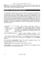
Page 14: ...temperature of the returning medium is exceeded the element responsible for maintaining the required temperature downstream from the mixer takes over control The temperatures are set in the HEATING s...

Page 15: ...ine with the adjustment guidelines included in Table No 1 Adjustment guidelines PROBLEM ADJUSTMENT Room temperature is too low within the whole range of outdoor temperatures Increase the curve offset...

Page 16: ...or M RS 420 ESTYMA control unit 16 SYMBOL INSTALLATION TYPE A Floor heating system B Low temperature heating system C Heating system with temperature exceeding 75 C Table 2 Heating system types Figure...

Page 17: ...Operation manual for M RS 420 ESTYMA control unit 17 Figure 8 Heating curve offset Figure 9 Modification of heating curve slope...

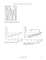
Page 18: ...air for 20 40 60 80 100 of the burner power The values will be calculated by approximation method from the selected curves See Figure 11 If the control system includes the optional Lambda module oxyge...

Page 19: ...Operation manual for M RS 420 ESTYMA control unit 19 Figure 10 POWER TEST submenu Figure 11 Blower power curve Figure 12 Blower power curve with Lambda based control...

Page 20: ...MODE submenu The hot water pump runs only when the temperature of the heating medium in the boiler is higher than the water temperature in the hot tap water tank In this way losses of energy stored in...

Page 21: ...default setting if the hot water pump runs for more than 20 min default setting and the set hot tap water temperature is not attained The relevant SERVICE MODE submenu parameters are stop HP hwp and...

Page 22: ...eeder are controlled manually ON the control unit is on NOTE When OFF is displayed on the screen the control unit is actually in a standby mode and is energized in case of an alarm the control unit wi...

Page 23: ...ess to turn the feeder on off Press to turn suction on off After you press the button the feeder will run for 30 seconds filling the retort with fuel about half way Once this happens turn the boiler c...

Page 24: ...unit s memory no flame no fuel the alarm is activated when there is no fuel or no flame in the burner check suction system the alarm is activated if the suction system has made three consecutive fail...

Page 25: ...r pump 100W Lighter 400W Blower 150W Feeder motor 200W Automatic exchanger cleaning suction motor 100W Mixer actuator 50W Boiler temp setting range 60 85 C Hot tap water setting range 35 70 C Temperat...

Page 26: ...Operation manual for M RS 420 ESTYMA control unit 26 estyma electronics Gajewo Al Lipowa 4 11 500 Gi ycko POLAND phone 48 87 429 86 75 fax 48 87 429 86 75 biuro estyma pl www estyma pl...

Reviews: