Summa Series Servodrive Product Manual
Tuning
Document Version: V1.01
(Dec, 2019)
© 2019 ESTUN Automation Co., Ltd. All right reserved.
9-28
If you keep the default setting of Pn162, you can use a low-pass filter to eliminate the noise and high-
frequency band, in this case, you shall set Encoder Speed Filter Time (Pn135) as a proper value.
Increase the setting of Pn135, the filtering effect will be better, and the encoder feedback speed will be
smooth, but the phase lag of the speed feedback is also larger, which can reduce the servo performance.
Parameter Setting
Meaning
When Enabled
Classification
Pn135
-
Encoder Speed Filter Time
Immediately
Adjustment
9.5
Additional Adjustment Functions
9.5.1
Gain Switching
Function Description
The gain switching function can be used for the manual tuning. It is required to switch from 1st gain
parameters to 2nd gain parameters for the Servo operation in a specific stage, so that the overall
performance of the Servo system can reach the desired performance.
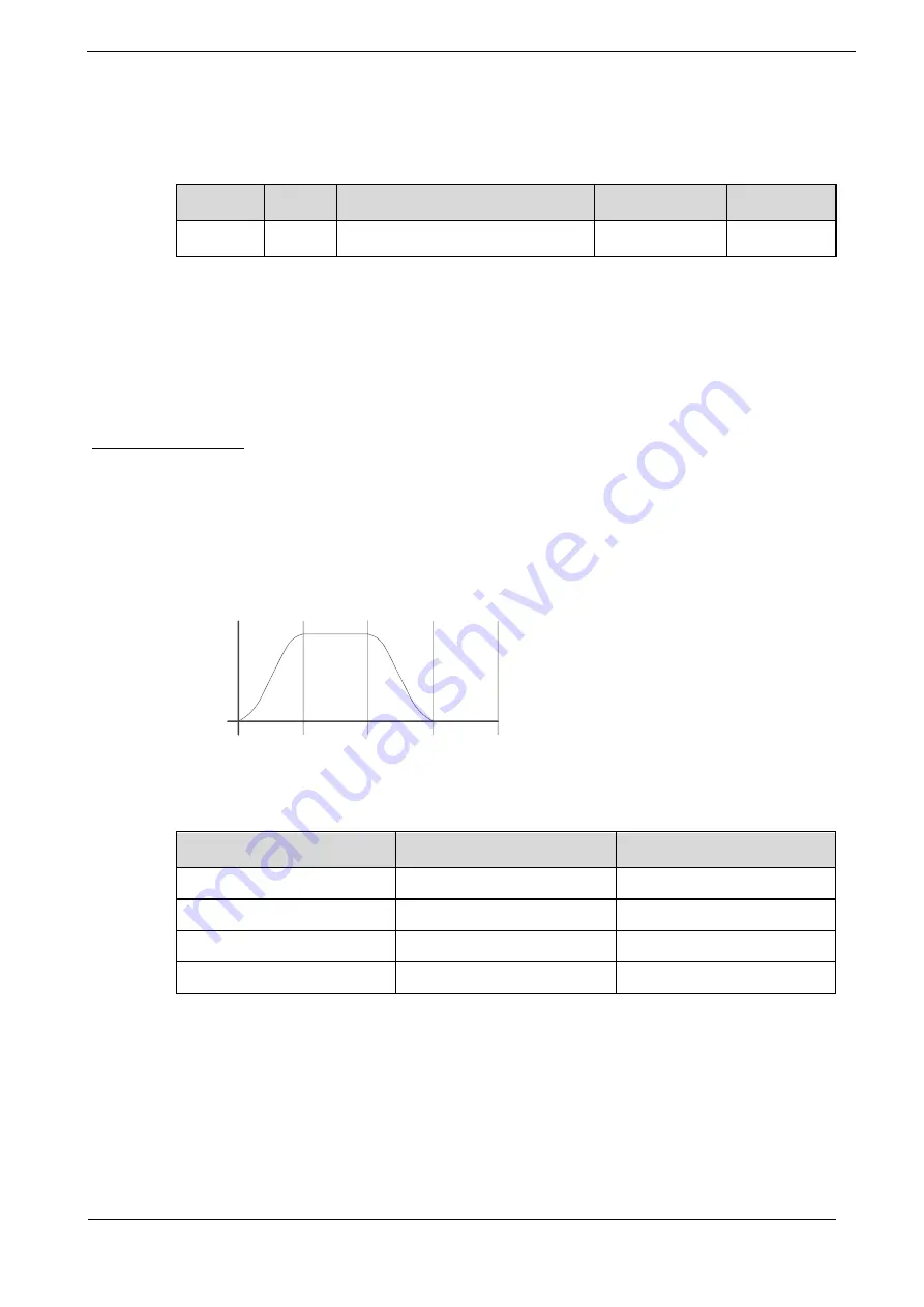
Take Figure 9-11 as an example, the position stage focuses on the performances such as position ripples
and positional rigidity, while the moving stage focuses on the performance such as following error. In
this case, two switchable groups of gain parameters are required to meet the Servo performance.
Figure 9-11
Gain switching example
Position
Moving
stage
1st gain 2nd gain
1st gain 2nd gain
Positioning
stage
Moving
stage
Positioning
stage
The parameters of the first gain and the second gain are as follows.
Parameter
First Gain
Second Gain
Speed Loop Gain
Pn102
Pn107
Speed Loop Integral Time
Pn103
Pn108
Position Loop Gain
Pn104
Pn109
Torque Command Filter Time
Pn105
Pn110
The gain switching function includes two settings: one is the conditions for starting the gain switching
and the other is which process to start the gain switching. Figure 9-12 shows a timing diagram for the
gain switching.


