background image

 /195M (TNB) 


USER’S MANUAL


Revised: 30 Jan 2018 

4 of 10


Programming 


The /195M (TNB) system uses the same ESTeem Narrowband Configuration Utility  for configuration and 
monitoring as the ESTeem Model 195M by itself. 


The ESTeem Narrowband Configuration Utility (a component of the ESTeem Discovery Suite) will allow easy access 
to the configuration, monitoring and diagnostics for the /195M (TNB) system. 
 

Installation  

 
The Discovery Suite can be downloaded from the ESTeem web site 
(

http://www.esteem.com

) or is available on the Software Resource media that 

was shipped with the radios. 
 
1.


The Discovery Utility is a Java™ based application compatible with any 

computer operating system (Window, Linux, etc). The application requires 
two (2) additional support files to operate: 


Java 

 Downloadable from 

http://www.java.com

. The version required will be based upon your operating system. 

Note: The installation and updates from Java may try and install additional web browser toolbars.  Uncheck the 
optional installation if they are not desired.  
 

WinPcap


 Downloadable from 

http://www.winpcap.org/

.  The version required will be based upon your 

operating system.   


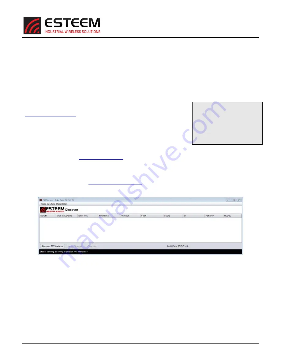
Figure 4: ESTeem Discovery Utility 

2.


Once both the above programs have been installed, save the ESTeem.exe file to any location on your 
computer such as the Desktop.  Double click the ESTeem.exe program and Figure 2 will be displayed. 

 
3.


Connect the /195M (TNB) system to your computer either directly to the Ethernet card or through a 
Switch using a CAT-5e Ethernet cable.  The Ethernet port supports Auto-Negotiation, so either a patch cable 
or crossover cable will work.  Press the 

Discover EST Radios

 button.  This discovery utility and imbedded 

ESTeem Narrowband Configuration Utility will be used throughout the remainder of the User’s Manual.


4.


The ESTeem 195M will be displayed (Figure 5).  If the ESTeem is not on the same IP subnet as the computer, 
double click on the IP, Netmask or Gateway and make the necessary changes.  Press the 

Apply Changes


button when complete. 

Technical  Tip

If  your  computer  is 

configured  for  DHCP  and  not 
attached  to  the  network,  you  will 
need to assign a static IP address to 
program  the  /195M  (TNB) 
system. 
 

Summary of Contents for Radius+/195M

Page 1: ...ESTeem Industrial Wireless Solutions Radius 195M TNB High Output Power System User s Manual ...

Page 2: ...ems Technology Inc All rights reserved Printed in the United States of America No part of this publication may be reproduced stored in a retrieval system or transmitted in any form or by any means electronic mechanical photocopying recording or otherwise without the prior written permission of Electronic Systems Technology Author Date Name Eric P Marske Title Product Manager Approved by Date Name ...

Page 3: ...rface SDI configuration modes RS 232 The ESTeem 195M has two 2 RS 232 data ports The primary RS 232 port Port 3 has full hardware handshaking through the request to send RTS and clear to send CTS lines Both RS 232 ports are software configurable from 2 400 to 115 000 bps RS 422 The ESTeem 195M has a single RS 422 data port Port 2 The RS 422 data port is shared on the front panel with the 10 100 Mb...

Page 4: ...f 10 Diagrams The following diagrams show the ESTeem Model 195M to Radius interface and details on the front panel Figure 1 Connection Diagram Throughout this tutorial Technical Tips have been added to help in programming and answer some common questions ...

Page 5: ...RADIUS 195M TNB USER S MANUAL Revised 30 Jan 2018 3 of 10 Figure 2 Front Panel Diagram Figure 3 195M Front Panel ...

Page 6: ...ional installation if they are not desired WinPcap Downloadable from http www winpcap org The version required will be based upon your operating system Figure 4 ESTeem Discovery Utility 2 Once both the above programs have been installed save the ESTeem exe file to any location on your computer such as the Desktop Double click the ESTeem exe program and Figure 2 will be displayed 3 Connect the Radi...

Page 7: ...red when the 195M Configuration Utility is opened If the utility was opened through the Discovery program the current configuration parameters for the modem will be displayed Figure 7 If the 195M information is not displayed press the Read Config button to continue The majority of the radio s configuration can be entered from the Configuration tab Setting the modem s address destination frequency ...

Page 8: ...display status information such as the forward and reflected power ratio and allow modification of the software commands Figure 8 Utility Console Firmware Updates The Radius amplifier can update the firmware through the utility if new features for updates are added in the future Select the to the Firmware tab and press Update Firmware button to complete If the firmware version is up to date the me...

Page 9: ...NUAL Revised 30 Jan 2018 7 of 10 Figure 9 Firmware Update Advanced Configuration The Radius amplifier will display the status of all software commands if Read Config button is pressed Figure 10 Figure 10 Advanced Configuration ...

Page 10: ...577 0 fwd rev ratio 708 2 The ratio number will change based upon hardware conditions environmental conditions and overall power output but the ratio number is not directly related to a percentage or power value It is best used as a long term indicator of the heath of the transmission system As the number approaches 0 lower ration numbers the higher the reflected power is detected There is a softw...

Page 11: ... ID field for the amplifier This can be set to any alphanumeric value such as site name location or serial number This value will be displayed in the Discovery Utility under ID see figure 6 pcbtemp This command will measure the internal temperature of the Radius amplifier The temperature will be displayed in both Celsius and Fahrenheit reflect 0 2000 This software command will set the maximum refl...

Page 12: ...50 ohms Rx Insertion Loss 0 7dB FCC ID ENPRADPVHF LED Indicators Power Transmit Ethernet Activity Link Power Requirements Receive 90 mA 13 8 VDC Transmit 30 Watts RF Output 4 9A 13 8 VDC External DC Power Input 12 to 14 VDC External DC Power Supply AA176 Input Output Connectors Ethernet Port 10 100 RJ 45 Female Serial Data Interface RS 232 9 600 Baud External DC Input Power Switchcraft 2 5mm ID 5 ...

Reviews: