background image

Equipment Enclosures Manual 


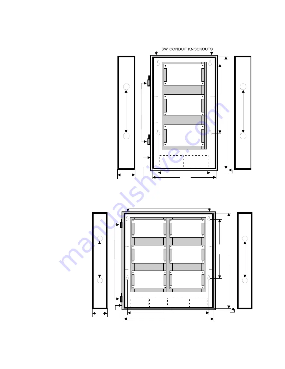
CAB-3F 

AA75 SERIES

AMPLIFIER

BATTERY

BATTERY

CONTROL MODULE

CM1(N) - CM2(N)

POWER SUPPLY

PS4/8B

REMOVABLE BACK PANEL

29

.2

5"

3

/4

" CONDUIT

 KN
OCKO

UT
S

3/

4"

 CONDU

IT

 KNOCK

O

UT

S

HI

N

G

E

S

18.
00

"

12.75"

15.00"

4.25"

SIDE

FLANGE

SIDE

[CAB-003.CDR]

0.75"


CAB-6F 

OPTION MODULE

AA75 SERIES

AMPLIFIER

6.5 AH MAX.

BATTERY

6.5 AH MAX.

BATTERY

6.5 AH MAX.

BATTERY

6.5 AH MAX.

BATTERY

CONTROL MODULE

CM1(N) - CM2(N)

CONTROL MODULE

CM2(N)

POWER SUPPLY

PS4/8B

CONTROL MODULE

CM2(N)

REMOVABLE BACK PANEL

REMOVABLE BACK PANEL

3

/4"

 CO

N

DUIT

 K

N

OCK

O

U

T

S

3

/4"

 CO

N

DUIT

 K

N

O

CK

O

U

T

S

3/4" CONDUIT KNOCKOUTS

HI

N

G

E

S

4.25"

FLANGE

28.16"

0.75"

25.92"

SIDE

SIDE

[CAB-004.CDR]

29

.25

"

18.
00"


firealarmresources.com

Summary of Contents for BC-1

Page 1: ...P N 270244 Revised 14JUL97 Equipment Enclosures Installation Manual firealarmresources com ...

Page 2: ...anual without express written permission from EST This manual contains proprietary information intended for distribution to authorized persons or companies for the sole purpose of conducting business with Edwards Systems Technology Inc If you distribute any information contained in this manual to unauthorized persons you have violated all distributor agreements and we may take legal action CREDITS...

Page 3: ...i Flush 19 Rack Enclosures 5 Description 5 Application 5 Layout 6 Specifications 7 Installation 8 MFC Enclosure 12 Description 12 Application 12 Installation 12 BC 1 Battery Cabinet 14 Description 14 Application 14 Specifications 14 Dimensions 15 RKU Series 19 Inch Equipment Racks 16 Applicable Racks 16 Description 16 Application 16 Specifications 17 firealarmresources com ...

Page 4: ...tial damages arising from loss of property or other damages or losses owing to the failure of EST Inc products beyond the cost of repair or replacement of any defective products EST Inc reserves the right to make product improvements and change product specifications at any time While every precaution has been taken during the preparation of this manual to ensure the accuracy of its contents EST a...

Page 5: ... Document history Equipment Enclosures Installation Manual P N 270244 Revision Status Revision Date Reason For Change 1 0 September 1995 Re write of old manual 1 5 July 1997 Major revision of layout and content firealarmresources com ...

Page 6: ...iv Equipment Enclosures Manual firealarmresources com ...

Page 7: ...red with a standard key lock assembly All enclosures feature mounting studs for mounting a door tamper switch which is required for security panel operations Door assemblies and back boxes are painted white Red enclosures may be specified by adding an R suffix to part and model numbers Electrical knockouts are provided on the top bottom and sides of the back box and keyhole mounting slots are loca...

Page 8: ...EL 12 00 12 00 4 81 SIDE SIDE 15 00 23 00 3 4 CONDUIT KNOCKOUTS 3 4 CONDUIT KNOCKOUTS 3 4 CONDUIT KNOCKOUTS HINGES CAB 001 CDR CAB 3 AA75 SERIES AMPLIFIER BATTERY BATTERY CONTROL MODULE CM1 N CM2 N POWER SUPPLY PS4 8B REMOVABLE BACK PANEL 29 25 3 4 CONDUIT KNOCKOUTS 3 4 CONDUIT KNOCKOUTS HINGES 18 00 12 75 15 00 4 81 SIDE SIDE CAB 002 CDR firealarmresources com ...

Page 9: ...GE SIDE CAB 003 CDR 0 75 CAB 6F OPTION MODULE AA75 SERIES AMPLIFIER 6 5 AH MAX BATTERY 6 5 AH MAX BATTERY 6 5 AH MAX BATTERY 6 5 AH MAX BATTERY CONTROL MODULE CM1 N CM2 N CONTROL MODULE CM2 N POWER SUPPLY PS4 8B CONTROL MODULE CM2 N REMOVABLE BACK PANEL REMOVABLE BACK PANEL 3 4 CONDUIT KNOCKOUTS 3 4 CONDUIT KNOCKOUTS 3 4 CONDUIT KNOCKOUTS HINGES 4 25 FLANGE 28 16 0 75 25 92 SIDE SIDE CAB 004 CDR 2...

Page 10: ... Finished Width 15 15 16 15 16 30 Finished Depth 4 81 4 81 75 75 Back Box Height 23 29 25 29 25 29 25 Back Box Width 15 15 15 28 5 32 Back Box Depth 4 81 4 81 4 25 4 25 Backplane Module Spaces 2 3 3 6 Side Wall 1 2 Module Mounting 2 2 2 2 Battery Allocation 2 x 6 5 AH 2 x 6 5 AH 2 x 6 5 AH 4 x 6 5 AH firealarmresources com ...

Page 11: ...at installed directly in the rack The removable enclosure door is secured in an integral pan frame and may be hinged on either the left or right side The door is provided with a Lexan insert for viewing system annunciators and is secured with a standard key lock assembly Mounting studs are provided for mounting a door security switch which is be required for security panel operations Backboxes are...

Page 12: ...7 5 VERTICAL RACK SPACE 19 RACK MOUNT MOUNTING RAILS NOTE DASHED LINES INDICATE SEMIFLUSH LINES CAB 005 CDR CB31 BACKBOX 31 5 VERTICAL RACK SPACE 19 RACK MOUNT MOUNTING RAILS NOTE DASHED LINES INDICATE SEMIFLUSH LINES CAB 006 CDR firealarmresources com ...

Page 13: ... NOTE DASHED LINES INDICATE SEMIFLUSH LINES CAB 007 CDR Specifications Enclosure Dimensions CB17 CB31 CB45 Finished Height 27 7 8 70 8 cm 41 7 8 106 4 cm 55 7 8 141 9 cm Finished Width 27 5 8 70 2 cm 27 5 8 70 2 cm 27 5 8 70 2 cm Finished Depth 8 20 3 cm 8 20 3 cm 8 20 3 cm firealarmresources com ...

Page 14: ...ackplane height indicates the clearance required in front of backplane mounted components The sum of the rack depth and backplane height can not exceed 5 75 inches Component Dimensions Component Vertical Rack Space Rack Depth Backplane Height AA75 N A N A 3 5 ACP 12 25 5 5 N A ACP 6 19 25 5 5 N A APS8B N A N A 3 0 ARM 8 N A N A 3 0 BP1 1 75 N A N A BP2 3 5 N A N A BP3 5 25 N A N A CM1N CM2N USE RM...

Page 15: ... CAB 008 CDR 17 00 3 60 2 00 17 50 20 50 9 00 21 19 6 81 20 50 24 19 9 00 24 19 CABINET MOUNTING HOLES 3 4 CONDUIT KNOCKOUTS 3 4 CONDUIT KNOCKOUTS 1 1 2 1 25 2 00 INSIDE W O DOOR SIDE VIEW TOP AND BOTTOM VIEW NOTE DASHED LINES INDICATE SEMI FLUSH TRIM 27 62 8 00 Note Backbox rough in depth 5 7 8 firealarmresources com ...

Page 16: ...50 12 50 21 19 6 81 34 50 24 19 12 50 24 19 CABINET MOUNTING HOLES 3 4 CONDUIT KNOCKOUTS 3 4 CONDUIT KNOCKOUTS 1 1 2 1 25 2 00 INSIDE W O DOOR SIDE VIEW TOP AND BOTTOM VIEW NOTE DASHED LINES INDICATE SEMI FLUSH TRIM 1 0 27 62 8 00 Note Backbox rough in depth 5 7 8 firealarmresources com ...

Page 17: ...50 48 50 19 50 21 19 6 81 8 00 48 50 24 19 19 50 24 19 CABINET MOUNTING HOLES 3 4 CONDUIT KNOCKOUTS 3 4 CONDUIT KNOCKOUTS 1 1 2 1 25 2 00 INSIDE W O DOOR SIDE VIEW TOP AND BOTTOM VIEW NOTE DASHED LINES INDICATE SEMI FLUSH TRIM 1 0 Note Backbox rough in depth 5 7 8 firealarmresources com ...

Page 18: ...or remote mounting of an RZB12 6 or UIO 12 module Low profile full footprint modules may also be mounted in the MFC using the RZMP mounting plate adapter Installation Installation must allow for cable and wire access and for removal of the front cover Use of the RZMP mounting plate adapter will permit low profile full footprint modules such as an ARM 8 without cover to be mounted in the MFC MOUNTI...

Page 19: ... TAMPER SWITCH MOUNTING SCREWS RZB INSTALLATION MFC CAB 012 CDR RZB MFC Installation 1 1 7 2 3 4 5 6 7 4 3 5 3 2 6 RZB P C BOARD MOUNTING PLATE SLOTTED PAN HEAD SCREW 6 32X3 8 LOCK WASHER 6 HEX NYLON STANDOFF 6 32X1 2 SLOTTED PAN HEAD SCREW 6 32X1 4 CABINET BACKPLATE RZB RZMP INSTALLATION CAB 013 CDR NOTE EXTRUDED PRESS NUTS FACE REAR RZB RZMP Installation firealarmresources com ...

Page 20: ... slots on the back panel Application The BC 1 is designed for housing large batteries which are too large to fit inside standard surface and semi flush mounted enclosures Cabinets may be bolted together vertically to increase capacity Specifications Specifications Material 16 Gauge Steel Finish Off White Dimensions 14 x 18 25 x 7 25 H W D BC 1 Battery Cabinet Capacity Battery P N Voltage Amp Hour ...

Page 21: ...Equipment Enclosures Manual 15 Dimensions TERMINAL BLOCK AND FUSE 15 75 16 00 7 25 14 00 7 25 1 25 18 25 3 4 CONDUIT KNOCKOUTS 3 4 CONDUIT KNOCKOUTS TOP VIEW SIDE VIEW firealarmresources com ...

Page 22: ...stacking of multiple racks Six conduit knockouts for 1 2 in or 3 4 in conduit are available on the top end panel three on top three on the flange and six on the bottom end panel three on the bottom and three on the flange Three 2 875 in 7 3 cm diameter cable access holes are located on the bottom end panel for routing wiring to cabinet components the equipment mounting rails on the front of the ra...

Page 23: ... 375002 22 31 in 56 7 cm 65 56 in 166 5 cm 18 50 in 47 0 cm 61 25 in 155 6 cm 114 lbs 51 8 kg RKU 61B P N 375002B 22 31 in 56 7 cm 65 56 in 166 5 cm 18 50 in 47 0 cm 61 25 in 155 6 cm 114 lbs 51 8 kg RKU 70 P N 375003 22 31 in 56 7 cm 74 31 in 188 7 cm 18 50 in 47 0 cm 70 00 in 177 8 cm 130 lbs 59 0 kg RKU 70B P N 375003B 22 31 in 56 7 cm 74 31 in 188 7 cm 18 50 in 47 0 cm 70 00 in 177 8 cm 130 lb...

Page 24: ...18 Equipment Enclosures Manual firealarmresources com ...

Reviews: