ESI Kata Series Installation Instructions Manual Download Page 5

Page 5

Kata Assembly

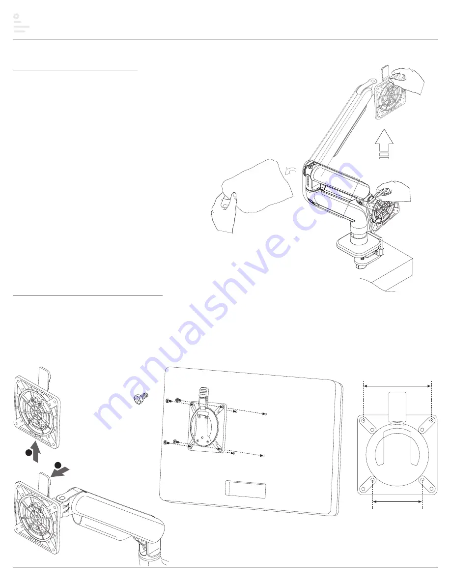
Step #3: remove the plastic bag

Hold the arm when you are removing the plastic bag to avoid the arm from bouncing.

push tab forward

lift off VESA plate

VESA plate screw

VESA

plate

monitor

(face down)

top

3.9"

(100mm)

3"

(75mm)

2

1

Step #4: attach VESA plate to monitor

•  Remove the VESA plate from the VESA mount by pushing forward on the tab at the top and lifting upward.


— TIP: Practice re-installing the VESA plate before attaching it to the monitor. This will make step 3 easier.

•  Place the monitor face down on a flat surface. Align the VESA plate holes with the holes on the back of the monitor. Attach the VESA plate using the four VESA plate 

screws provided.


— There are two sets of four holes on the VESA plate. One set has holes 3.9" (100mm) apart, the other set has holes 3" (75mm) apart. Use the set that matches the 

holes on the rear of the monitor.

Summary of Contents for Kata Series

Page 1: ...installation instructions Kata model s KATA DC SLV KATA DC BLK KATA DC WHT KATA GM SLV KATA GM BLK KATA GM WHT monitor arm...

Page 2: ...Page 2 Kata Intentionally left blank...

Page 3: ...on were provided with your order Do not discard the packaging until the product works to your satisfaction Components and tools Additional tools required Phillips screwdriver Caution Hand tighten scre...

Page 4: ...e worksurface Clamp the assembly to the worksurface in the desired position Be sure to tighten the clamp securely If using optional grommet mounting method Replace step 1 with step A on page 10 Then p...

Page 5: ...shing forward on the tab at the top and lifting upward TIP Practice re installing the VESA plate before attaching it to the monitor This will make step 3 easier Place the monitor face down on a flat s...

Page 6: ...mount Slide the VESA plate with monitor attached back onto the VESA mount Make sure the VESA plate clicks securely in place attach monitor VESA mount Step 6 remove cable management covers Slide the c...

Page 7: ...nitor arm Tighten the screw then back it off one turn To lockout rotation of the motion arm install a M4x15 set screw in one of the two holes in the underside of the fixed arm Tighten the set screw th...

Page 8: ...e 4mm end of the dual Allen key to adjust the screw at the top of the fixed arm for the appropriate monitor weight 4 Motion arm swivel adjustment Use the 4mm end of the dual Allen key to adjust the sc...

Page 9: ...cables and cords with the cable covers Slide the cable covers downward to attach them to the motion arm and fixed arm Snap the cable clip into groove on the base of the fixed arm Position the opening...

Page 10: ...bolt centered Fit the base cover over the base Insert the grommet bar onto the grommet bolt and then screw on the grommet knob Tighten the grommet knob securely to hold the base assembly in position G...

Page 11: ...Page 11 Kata...

Page 12: ...y implied warranty and the purchaser s sole remedy is limited to the repair or replacement at ESI s option of the product or any defective part Costs such as installation labor fees or express shippin...

Reviews: