2
AA780DAT ARTICULATING KEYBOARD ARM
PLEASE REVIEW
these instructions before beginning the installation. Check that
all parts needed were provided with your order. Contact your supplier if any
operates to your satisfaction.
PARTS PROVIDED
TRACK M
OUN
TING T
E MPL
A TE
FR
O
N
T E
D
G
E
OF
W
O
RK
SU
RF
A
CE
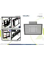
1. Tap
e this
mount
ing tem
plate to t
he und
erside o
f work
surfac
e.
2. Dril
l two (
2) 1/8"
diamet
er x 1/
2" dee
p pilot
holes
at mar
ked lo
cations
. Be ca
reful n
ot to
drill th
rough
the wo
rk surf
ace.
3. Rem
ove tem
plate a
nd insta
ll two (
2) #12
x 3/4"
wood
screws
into p
ilot hol
es. Lea
ve a ga
p
of app
roxima
tely 1/
8" betw
een th
e head
of eac
h scre
w and
work s
urface
.
4. Slid
e track o
nto scr
ews, u
sing t
he key
holes i
n the t
rack. T
ighten
the sc
rews a
nd insta
ll
additi
onal sc
rews a
s requ
ired, m
inimum
of fou
r (4).
Note: I
f keyboa
rd tray
is dee
per than
12", m
ount b
asefra
me a f
urther
1/2" b
ack fro
m the f
ront
edge o
f work
surfac
e.
1/8" P
ilot Ho
le
1/8" P
ilot Ho
le
Articulating Arm (1)
Track (1)
12x
3
/
4
" Screws (8)
10x
3
/
8
" Screws (2)
Front Stop (1)
Template (1)
Tape to Underside
of Work Surface
Note:
This install
requires a powertool
or cordless drill. This is
not a handtoolinstall.
ADDITIONAL TOOLS REQUIRED
• Drill with
1
/
8
" bit
• #2 Phillips bit
STEP 1: Use Template to Drill Pilot Holes
• Tape the template to the underside of the work
surface. Align the “front edge” line on the
template with the front edge of the
work surface.
• Drill
1
/
8
" pilot holes through the
two marked locations on the
template.
— Drill the holes
5
/
8
" deep
CAUTION:
Be careful not to drill
through the work surface.
• #3 Phillips bit


