background image


*


if the sensor or actuator supports Auto-E-Connect. For details, please refer to the operating instructions of the sensor or actuator. 

All rights reserved. Reproduction as well as electronic duplication of this user guide, complete or in part, requires the written consent of 
ESERA GmbH. Errors and technical modification subject to change. 



ESERA GmbH 2021 

www.esera.de 

11603-48  V1.0 R1.1 Manual 

Page 10 of 18 

14 

Interface configuration Modbus/TCP, Maxi Interface 

Important, at present the configuration of the Ethernet interfaces is only possible via the web interface. The IP 
address for starting the web server is shown on the unit display or can be found in the system overview of the 
router / DHCP server. 
 

14.1 

Maxi Interface, Web server 

The ECO controllers with Maxi interface, e.g. ECO 208, have a web server for configuring the Ethernet interfaces 
(LAN and WLAN). 
The ECO Controller with Maxi interface logs into your network with the identifier "ESERA". The Ethernet interface 
is set to "DHCP" in the delivery state. 


14.2 

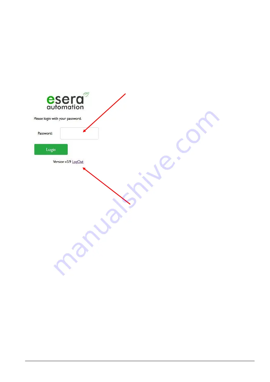
Web server, LogIn 


Password, LogIn 

In order to be able to log into the web server of the 
ECO Controller, use the following password for the 
initial login: 


eserapwd 


For security reasons, the password is not displayed in 
plain text but with dots.  
 

Important: Please change the password after the 
first login, otherwise unauthorised persons can 
make settings on the ECO Controller.  
Please enter a new and secure password via the 
main menu, button "Change Password". 
You can find information on assigning secure 
passwords on the Internet. 

 
After entering the password, click on the "Login" button 
to open the main menu (hereinafter referred to as 
Main Menu). 
 

Software status Ethernet interface / LogOut 

Display of the software version of the Ethernet 
interface installed on the unit. You can see the version 
of the 1-Wire Firmware via Config Tool 3. 
 
Click on the "LogOut" button to exit the web interface. 

Summary of Contents for ECO 208 PRO

Page 1: ...relay output alarm output Plug and Play interface for up to 30 sensors e g temperature humidity air quality gas sensors Web server for configuration Debug and Firmware updates robust industrial design extensive software support power supply 48VDC Auto E Connect Support Level I to III Fast readout of all 1 Wire Devices in a 1 2 seconds cycle Basic unit for many industrial and telecommunication solu...

Page 2: ...1 Wire devices The ECO 208 PRO independently scans the 1 Wire Network for new 1 Wire devices reads their Auto E Connect data automatically adapts the device libraries and outputs the adapted data in plain text adapted to the scanned 1 Wire devices Designed for all 1 Wire Networks The 1 Wire interface of the ECO 208 PRO is specially designed to safely operate small up to very large 1 Wire Networks ...

Page 3: ...eady formatted data is output The Auto E Connect functionality will be available for the ECO Controller and ESERA Station 200 Pro from 2021 Auto E Connect Level I OWD Detect Detection of new sensors and actuators and automatic start of adapted libraries Auto E Connect Level II Visualise product data Readout and visualisation of Auto E Connect and manufacturer data of sensors and actuators such as ...

Page 4: ...g in terminals up to 2 5qmm cable cross section Output voltage 5V 10 max 300mA overload overvoltage and short circuit proof Isolation Galvanic isolation between Ethernet and 1 Wire Interface Supported DS2401 DS1963 DS1990 DS1820 DS18S20 DS18B20 DS2413 DS2438 DS2450 1 Wire devices DS2408 DS2405 DS2406 only input DS2423 other chips on request We will be happy to support other components as an OEM pr...

Page 5: ...Errors and technical modification subject to change ESERA GmbH 2021 www esera de 11603 48 V1 0 R1 1 Manual Page 5 of 18 LED Green WLAN WLAN Network Status LED lights up when a WLAN Network connection is established flashes when the WLAN access point is activated and a direct connection is possible 8 Connection plan Module top side Digital inputs normally open contacts Reset Button Reset Button for...

Page 6: ...et button of the system When the button is pressed the unit is restarted The stored data is retained but all connections are Interrupted This keystroke does not correspond to an interruption of the power supply Note The module may only be operated at the voltages and under the ambient conditions specified for it The operating position of the unit is arbitrary The modules may only be put into opera...

Page 7: ...sensor or actuator All rights reserved Reproduction as well as electronic duplication of this user guide complete or in part requires the written consent of ESERA GmbH Errors and technical modification subject to change ESERA GmbH 2021 www esera de 11603 48 V1 0 R1 1 Manual Page 7 of 18 10 Connection example 1 Wire Multisensors ...

Page 8: ...n also communicate at any time with any terminal program e g z B Hercules oder Putty via UDP TCP IP to exchange data with the ECO 208 PRO and to carry out the configuration Details on the communication commands can be found in the document Programming Manual which you can find in the download area of the ECO 208 PRO and within the Config Tool 3 software 12 1 ESERA ASCII Textprotokoll The ECO 208 P...

Page 9: ...und in the Programming Manual in the download area of the ECO 208 PRO and within the Config Tool 3 software Excerpt Modbus adress description Description Read address Number of words 16Bit Data type Gateway No 60000 1 Word Article No 60001 1 Word Firmware Version 61000 4 String Hardware Version 61010 3 String Serial number 61020 9 String Time 61030 4 String Date 61035 4 String 1 Wire Bus Sensors a...

Page 10: ... LAN and WLAN The ECO Controller with Maxi interface logs into your network with the identifier ESERA The Ethernet interface is set to DHCP in the delivery state 14 2 Web server LogIn Password LogIn In order to be able to log into the web server of the ECO Controller use the following password for the initial login eserapwd For security reasons the password is not displayed in plain text but with ...

Page 11: ... 2 5 In this menu you can set the port number of the Modbus TCP interfaces for example Disable AP Modus This button is only visible if the access point is activated To deactivate the WLAN access point press the Disable AP Mode button or press the WLAN Mode button at least 3 seconds on the front panel of the unit If the access point is not activated this button is not visible You can only activate ...

Page 12: ...mask and the gateway IP address are set here TCP Server or UDP operating mode With this selection the basic operating mode for the ECO Controller Maxi Interface is set Port The port address is assigned for socket 1 the ESERA ASCII protocol The port can be selected in the range 1 50000 The default port is 5000 DHCP Manual Operating mode IP address assignment You can choose between automatic DHCP an...

Page 13: ...protocols can be integrated here and made selectable We will be happy to provide you with an offer for the integration of further protocols Protocol and Port for Socket Data connections Interface 1 ASCII Protocol Interface 1 is permanently reserved for a TCP IP or UDP socket data connection via ESERA ASCII text protocol The port for this interface is set on the Interface Settings page Interface 2 ...

Page 14: ...surface To activate the access point press the WLAN Mode button for approx 3 seconds Activation is confirmed by the LED and the display Now you can connect to the ECO Controller using a WLAN capable device with a web browser To do this select the access point ESERA The web server of the ECO Controller can be reached via the IP address 192 168 4 1 A data connection via ESERA ASCII and Modbus TCP ca...

Page 15: ...r and thus reduces the maximum network size According to our many years of experience and a lot of feedback from customers the following conservative recommendation can be made Maximum cable length 50 120m Number of 1 Wire devices no more than 20 22 pieces As linear a topology as possible without T junctions The topology in particular plays a major role If possible linear topology should be used T...

Page 16: ...we will be happy to help you Simply contact our support team by e mail at support esera de 17 Example for integration in Codesys We would be pleased to provide you with a test software for the integration of the ECO 208 PRO into the PLC software Codesys Please contact our technical support under support esera de 18 Example for integration in Siemens SPS For many years the Modbus TCP protocol has a...

Page 17: ... that the devices are disconnected from the power supply and electrical charges stored in the components inside the device have been discharged Live cables or wires to which the device or an assembly is connected must always be tested for insulation faults or breaks If an error is detected in the supply line the device must be immediately taken out of operation until the faulty cable has been repl...

Page 18: ...o have the original purchase price refunded or a reduction of the purchase price ESERA GmbH accepts liability neither for the constant and uninterrupted availability of the ESERA GmbH or for technical or electronic errors in the online offer We develop our products further and we reserve the right to make changes and improvements to any of the products described in this documentation without prior...

Reviews: