Art. No. 11325
All rights reserved. Reproduction as well as electronic duplication of this user guide, complete or in part, requires the written consent of
ESERA GmbH. Errors and technical modification subject to change.
ESERA GmbH, ESERA-Automation 2020
www.esera.de
11325 V2.0 R1.0 Manual
Page 3 of 8
Setup on Linux
Here is a short guide for Linux:
Bind device using the normal Bluetooth functions
Run hcitool scan and remember the MAC
Create /etc/bluetooth/rfcomm.conf file if necessary
recomm.conf add the following entry:
# RFCOMM configuration file.
rfcomm0 {
# Automatically bind the device at startup
bind yes;
# Bluetooth address of the device
device
00:12:6F:2B:B1:52
;
#Here you enter the MAC address of the 1-Wire Controller 1
# RFCOMM channel for the connection
channel 1;
# Description of the connection
comment "1-Wire_Controller1";
}
Device must of course be adapted.
rfcomm connect
00:12:6F:2B:B1:52
execute in the console.
Now the serial interface can be accessed with a normal terminal program. (/dev/rfcomm0 )
8
Display LED
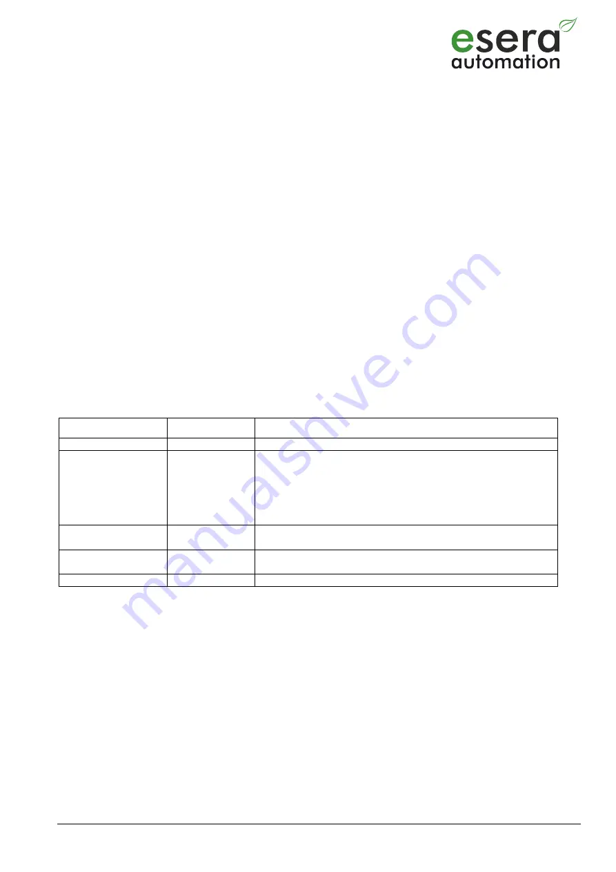
The module has various display LEDs. In the following the function of the displays
Display
Bezeichnung
Funktion
LED Green
PWR
Display for supply voltage
LED Green
DATA
After switching on the device the LED flashes 3x
flashes during 1-Wire activity
flashes when data is sent via the data interface
flashes very quickly if "CAL Receive" has been
activated and the "CAL messages" of the control
system are missing.
LED Green
Data interface
Network Link LED,
Lights up when a network connection is established
LED Green
Data interface
Network Data LED
Lights up during data communication via the data interface


