Overview
1. Overview
1.1 Description of VME-PMC-CPU/2
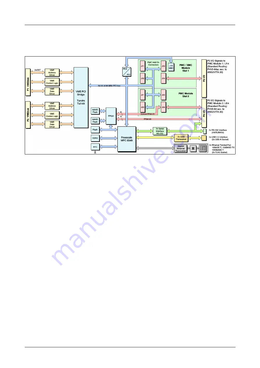
Fig. 1:
Block circuit diagram of VME-PMC-CPU/2 (V.1917.01, V.1917.02)
1.2 General
The VME-PMC-CPU/2 is a VME64-base board which can carry up to two PMC modules of normal
size. For the VMEbus connection the VME-PCI bridge Tsi148 by Tundra is used.
The Tsi148 is designed in a way that the board can either operate as slave or as master on the
VMEbus. If the board operates as master, it supports a 4-level arbiter. The VMEbus interrupt can
be applied to any of the seven interrupt-request lines. The first green LED signal indicates
VMEbus interrupt requests. The second green LED, which is located in the front panel, is active
during VMEbus access (not available for Conduction Cooled version). The VME-PMC-CPU/2 is
connected to the VMEbus by two 160-pin VG-connectors (acc. to DIN 41612) for VME64 systems
and one 95-pin I/O-connector (acc. to IEC 1076-4-101).
Both PMC slots are designed according to the standard IEEE Std 1386-2001 (except the standard
I/O pin routing). The slots are also designed for PPMC modules according to VITA32™. Slot 1 has
an XMC connector according to VITA42.3.
PMC modules, that use 3.3 V signalling only, can be used.
In addition to the connectors for the PMC address/data and control signals, every slot of the
VME-PMC-CPU/2 has an I/O-connector which applies the I/O-signals of the PMC modules to
VMEbus connectors P2 and P0.
The VME-PMC-CPU/2 is equipped with 2 USB-host interfaces (USB2.0) and 2 Ethernet interfaces
(IEEE802.3), which are accessible via front panel.
The front panel of the VME-PMC-CPU/2 has two cutouts for the front panels of the PMC modules.
A blank cover for unused slots is included in the scope of delivery.
Example libraries for the initialization of the board in C source code for VxWorks
®
are available for
a fee. Drivers for other operating systems are available on request. Please state your operating
system with the version number when you order.
VME-PMC-CPU/2
Hardware Manual • Doc.-No.: V.1917.21 / Rev. 1.2
Page 7 of 49


