


i
Overview
CAN-CBM-DP / DN-CBM-DP
Hardware-Manual • Doc.-No.: C.2844/6.21
/
Rev. 1.9
Page 9 of 45
!"#$%&
'
( )
*% !+,
-./- .0
.
1
2
3
45
678 &%9+
':; <
, :&&+ ,
8 '=
>?>@ A
BC @D?
CEF? DAC FG
-./- .
.
1
.H
.
I
JJJ
KLMN
OP
Q
R
S TUVWXY X
ZXW[\
] S^ U_
` a
bbcde af
VghZia
j c
^
k l
R
` a
bbcde af
L
O
OPQ
` amnbo
Sp ned qc
r
0s
st
0us
st
0u
v
ww x
y
zL
:{+ ,
8|}} &!
~
6
'
>?>@ A
BC @D?
CEF? DAC FG
] S^ U_
` a
bbcde a
f
87
67* %!+,
1. Overview
This manual describes the hardware of the CAN-interface CAN-CBM-DP and the hardware of the
DeviceNet-interface DN-CBM-DP module together. Differences are noted.
1.1 Module Description CAN-CBM-DP
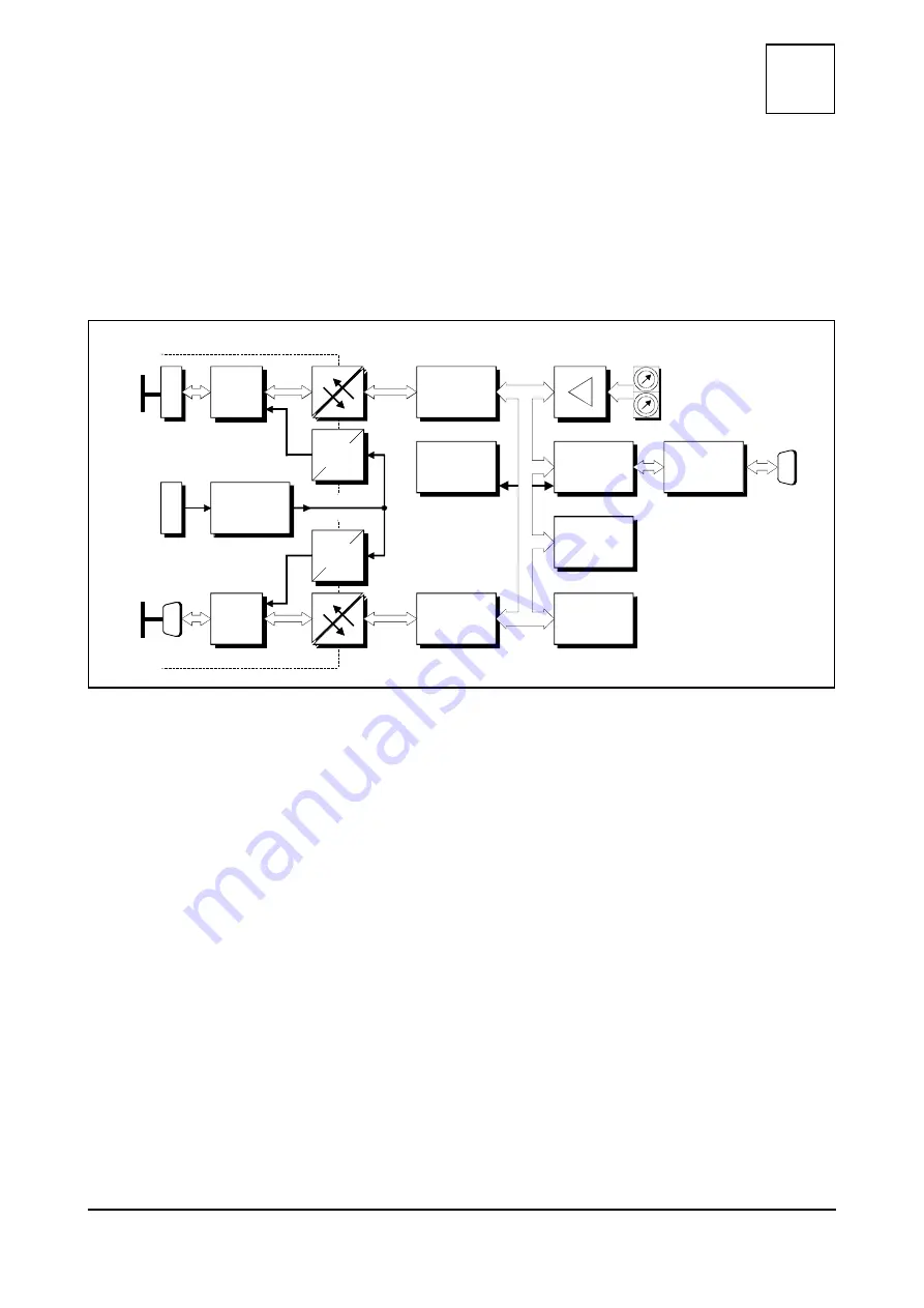
Figure 1: Block-circuit diagram of the CAN-CBM-DP module
By means of the module CAN-CBM-DP any Profibus-DP master can be connected to a CAN network.
The DP/CAN gateway acts like a slave I/O component on the DP-bus, with a total of up to 300 bytes
input and output data. Maximum 240 bytes of the total of 300 bytes can be used as input data (with 60
byte output data) or maximum 240 bytes can be used as output data (with 60 bytes input data).
The module operates internally with a 68331 micro controller, which buffers the CAN and Profibus DP
data into the local SRAM. The firmware and configuration data are kept in the Flash EEPROM.
Parameters are stored by means of a serial EEPROM.
The ISO 11898-compliant CAN interface allows a maximum data-transfer rate of 1 Mbit/s. The
Profibus-DP slave interface automatically recognizes all usual bit rates up to 12 Mbit/s.The DP interface
as well as the CAN interface are electronically insulated by optocouplers and DC/DC converters. CAN
is connected by means of a 5-pin screw/plug connector in Combicon design. According to standard, the
DP interface is equipped with a 9-pin female DSUB connector.
The CAN-CBM-DP can be configured with a PROFIBUS-tool as for example the SIMATIC Manager
S7 or the TIA Portal.
The module comes with a serial interface (default: RS-232) for servicing and configuration. It is
connected by means of a DSUB9 connector.