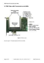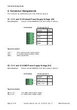
PCB View with Connectors and LEDs
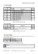
2.1 LED Indication
2.1.1 Power LEDs
LED
Colour
Indicator
State
Description
LED name
in schematic
diagram*
3.3V PCIe
green
off
3.3V power supply voltage off
LED230
on
3.3V power supply voltage on
12V PCIe
green
off
12 V power supply voltage off
LED220
on
12 V power supply voltage on
3.3V AMC
yellow
off
3.3 V AMC voltage off
LED241
on
3.3 V AMC voltage on
12V AMC
yellow
off
12 V AMC voltage off
LED240
on
12 V AMC voltage on
*The schematic diagram is not contained in the scope of delivery.
Table 1:
Description of the Power LEDs
2.1.2 User-LEDs
LED
Colour
Indicator
State
Description
LED name
in schematic
diagram*
USR1
yellow
software-
controlled
depending on software application used
LED140
USR2
red
LED141
*The schematic diagram is not contained in the scope of delivery.
Table 2:
Description of the User LEDs
2.2 Jumper Settings
With the jumper (J210) the operating mode can be switched from stand-alone operation to
software-controlled operation.
Jumper position Operating mode
open
stand-alone operation
closed
software controlled operation
See also PCB top view on page 8 for the position of the jumper.
Note!
Select the operating mode before you install the AMC-PCIe-Carrier in your computer.
AMC-PCIe-Carrier
Hardware Manual • Doc. No.: U.1003.21 / Rev. 1.1
Page 9 of 16


