


7. Installation Procedure
$
Also observe
Instrumentation Health Tips
chapter 14
105 mm
CONTROL
ESD - 9223
TEMPERATURE CONTROLLER
PRESS
I
II
542
E L E C T R O N I C S
SYSTEMS AND DEVICES
C
The instrument should be mounted in a place where it is clearly visible and
accessible.
1. Insert the instrument in the cutout and fix it using the bracket pair.
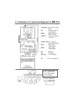
2. Depending on the type of instrument make connections as shown in
Connection diagram ( Chapter 6 ).
3. In case of Pt-100 sensor Red wire is to connected to the terminal indicated
with a Box.
4. In case of thermocouple input : (a) for
ESD
-9213
terminal no.8 has no
connection. (b) for
ESD
-9223
terminal no. 11 has no connection.
5. Use correct compensating cables for thermocouple type instruments.
6. Ensure proper earthing to the instrument.
7. Output loads connected through the relay change over contact should be
less than the maximum specified value.
8. Connect a series combination of 0.1
F /600 V non polar capacitor & 2 2 0
1/2 W resistor across phase & neutral.
9. For setting set values as per your requirement, press the push button and
rotate respective potentiometer with proper size screw driver.
10. If factory set control sensitivity (0.25% of FS) is not suitable for your
application, then adjust it by the potentiometer marked SENSITIVITY
(inside the instrument).
i) If relay chattering is observed, reduce the sensitivity by turning the
potentiometer Counter Clock Wise (CCW) .
ii) If over-shoots and under-shoots are observed increase the sensitivity by
turning the potentiometer Clock Wise (CW) .