


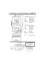


6.2 Schematic & Connection Diagram for
ESD
9223
CONTROL
- Red LED's for Relay
Status
SET
- Potentiomenters for
setpoint adjust
PRESS
- Press Switches to
read set values
DISPLAY
- 12.5 mm 7 segment
RED LED
VSEN1/ VSEN2
-
‘Sensitivity’
adjust Potentiometers
SPAN
-
‘Span’ adjust
Potentiometer
ZERO
-
‘Zero’ adjust
Potentiometer
IC1
- Amplifier
IC2
- Comparator
RL1, RL 2
- 12 V DC Relays
Pt-100 (3 WIRE RTD)
TC - THERMOCOUPLE
E
N
P
NC
P
NO NC
P
NO
C
C
R
R
C1
C2
1
2
3
4
5
6
7
8
9
SUPPLY
VOLTAGE
10 11 12
Pt 100
+
TC
Relay 1
Relay 2
2i
i
Display board
ESD - 9223DPM-R1
CONTROL SET
PRESS
DISPLAY
10 Pin connector
S
ec
o
n
d
a
ry
Sensitivity
S
p
a
n
Z
er
o
Transformer
ESD - 189
Relay2
Relay
Sensor
Primary
Backcard
ESD - 9223BK-R2
E N P
NC
P
NO
R G B
Relay1
NC
P
NO
Mother board
ESD - 9223MB-R2
TB
-
PBT Terminal board
TB
User Terminals
1 2
3
4
5
6
7
8 9 10 11 12