background image


13  

 |  

Assembly and Mounting Instructions 

4.0   Assembly and Mounting Instructions 


Before connecting any components, follow the 

safety information in the ETS-Lindgren 

Product Information Bulletin included with your 

shipment. 


Summary of Contents for ETS LINDGREN 3158

Page 1: ...Model 3158 High Power Biconical Antenna User Manual Model 3158 shown with pedestal...

Page 2: ...nder its patent rights or the rights of others Copyright 2000 2009 by ETS Lindgren L P All Rights Reserved No part of this document may be copied by any means without written permission from ETS Lindg...

Page 3: ...ptics 9 Service Procedures 10 3 0 Specifications 11 Electrical Specifications 11 Physical Specifications 11 4 0 Assembly and Mounting Instructions 13 5 0 Typical Data 17 Data from MIL STD 461F RTCA DO...

Page 4: ...iv This page intentionally left blank...

Page 5: ...ions could result in minor personal injury and or property damage Included text gives proper procedures Warning Denotes a hazard Failure to follow instructions could result in SEVERE personal injury a...

Page 6: ...vi This page intentionally left blank...

Page 7: ...in Radiated Susceptibility testing The biconical elements are made from welded aluminum tubing The 4 to 1 ratio balun network is fabricated from G10 fiberglass and specially machined brass and alumin...

Page 8: ...ct Information Bulletin included with your shipment for the following Warranty information Safety regulatory and other product marking information Steps to receive your shipment Steps to return a comp...

Page 9: ...tions concerning maintenance contact ETS Lindgren Customer Service Annual Calibration See the Product Information Bulletin included with your shipment for information on ETS Lindgren calibration servi...

Page 10: ...ntegrity Before connecting fiber optic cables clean the connector tips Before attaching connectors clean them with moisture free compressed air Failure to perform these tasks may result in damage to t...

Page 11: ...cations Frequency Range 20 MHz to 120 MHz VSWR Ratio Typical 2 1 Maximum 5 1 Maximum Input Power 5 kW Input Impedance 50 Connector 7 16 DIN female Physical Specifications Length 1 14 m 3 74 ft Width 3...

Page 12: ...Specifications 12 This page intentionally left blank...

Page 13: ...bly and Mounting Instructions 4 0 Assembly and Mounting Instructions Before connecting any components follow the safety information in the ETS Lindgren Product Information Bulletin included with your...

Page 14: ...element 2 Pedestal Belleville washer 2 Washer 4 and 5 16 1 1 4 hex bolt 4 Air solenoid nylon tube Fiber optic polarization cable Due to the size of the antenna you must mount the balun onto the pedest...

Page 15: ...r onto the threaded screw end of one of the biconical elements 4 Line up the screw threads on the element with the receptacle hole on the balun and turn the element until it is firmly secured in the b...

Page 16: ...neration ETS Lindgren controller if applicable is a separate component required for operation 7 Connect the fiber optic polarization cable to the polarization unit located on the back of the pedestal...

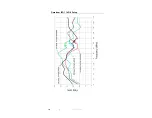
Page 17: ...17 Typical Data 5 0 Typical Data All data was measured in an ETS Lindgren FACT 3 chamber field for a 5 kW input Data from MIL STD 461F RTCA DO 160 Setup No Bench...

Page 18: ...Typical Data 18 MIL STD 461F RTCA DO 160 SETUP NO BENCH...

Page 19: ...19 Typical Data Data from ISO 11451 2 Setup...

Page 20: ...Typical Data 20 ISO 11451 2 SETUP...

Page 21: ...21 Typical Data Data from ECE Regulation 10 Setup Power input for 30 V m at 2 meters from the antenna and 1 meter over the ground...

Page 22: ...Typical Data 22 This page intentionally left blank...

Page 23: ...he complete ETS Lindgren warranty for your Model 3158 DURATION OF WARRANTIES FOR MODEL 3158 All product warranties except the warranty of title and all remedies for warranty failures are limited to tw...

Reviews: