


630184_4 IB Installation Manual NZ
33
26.1
Fitting the Fascia Panels:
To avoid scratches or knocks to the fascia panels of this heater they must be fitted at the
complete conclusion of the installation process. It may be necessary to use the outer fascia
to initially locate the heater but then remove it again
so that there is no chance of damage.
Note:
Never
Ever
Rub the Fascia Panels.
Step 1:
Replace the glass
Note:
If the glass gasket requires
a replacement, call your nearest
Escea agent who will ensure the part is
replaced with the correct type. In the event
that the glass is broken by impact, purchase
the replacement from an authorised
Escea agent only.
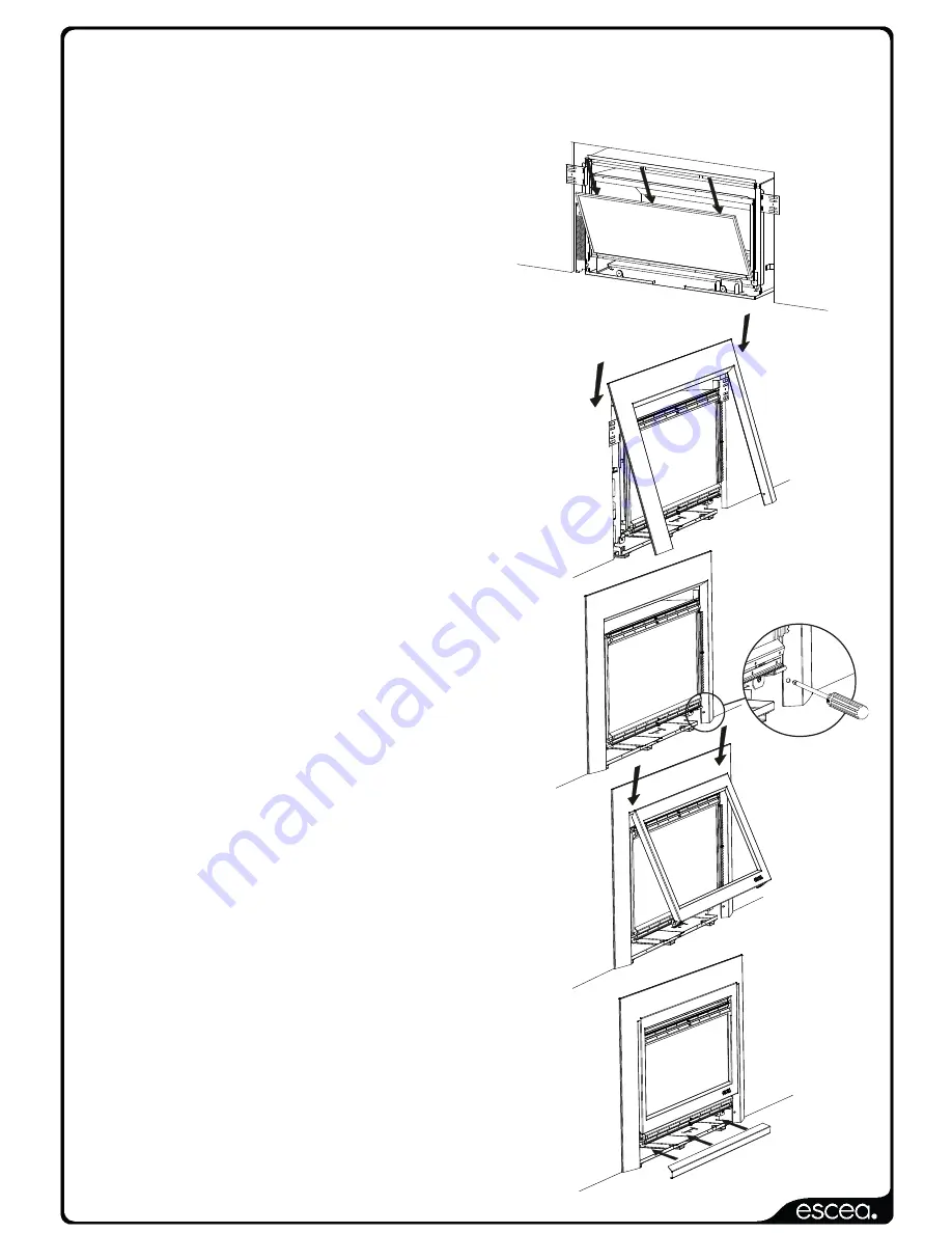
Step 2:
Hang the outer fascia (larger one)
from the lip that extends at the top
of the heater at 45 degrees.
If hanging a 4 sided fascia please
refer to sections 24.1 and 24.2
on the next page.
Step 3:
Fit the two screws at the base of
each side of this fascia. The heater
may have to be adjusted in or out
of the cavity to ensure the fascia fits
correctly.
Step 4:
Hang the top edge of the inner fascia
(smaller one) from the lip that extends
at 45 degrees from the top of the
firebox. This fascia is held in at its base
by magnets (IB850 & IB600).
Alternatively, this fascia is screwed to the
fire chassis (IB1100).
Step 5:
Place the bottom fascia trim into
position. This panel is held on
with magnets. If this panel does not fit,
adjust the outer fascia side to side or
the heater in/out until the trim fits well.


