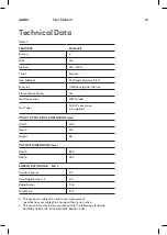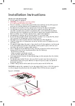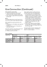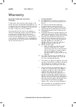
esatto.house
17
Gas Connection
Statutory requirements
This installation must conform with the following:
■ Manufacturer’s Installation instructions
■ Local Gas Fitting Regulations
■ Municipal Building Codes
■ Refer to AS/NZS 5601.1 for Gas Installations
■ S.A.A. Wiring Code
■ Local Electrical Regulations
■ Any other statutory regulations
Preparing to install
Refer to AS/NZS 5601.1 for piping size details. These built-in cooktops are intended to
be inserted in a benchtop cutout. Only an officially authorised technician should
connect the appliance. Before you begin, turn off the gas and electricity supply.
19
A full operational test and a test for possible leakages must be
carried out by the fitter after installation.
Access to the whole length of the connection hose must be possible
and the gas hose must be replaced before its use before the end of
service life (indicated on the hose.)
Before Leaving-Check all connections for gas leaks with soap and
water.
DO NOT use a naked flame for detecting leaks. Ignite all burners both
individually and concurrently to ensure correct operation of gas
valves, burners and ignition. Turn gas taps to low flame position and
observe stability of the flame for each burner individually and all
together. Adhere the duplicate data plate to an accessible location
near the hotplate. When satisfied with the hotplate, please instruct
the user on the correct method of operation. In case the appliance
fails to operate correctly after all checks have been carried out, refer
to the auth orised service provider in your area.
Natural gas connection
95
115
LPG gas connection
pressure test point
pressure test point
Figure 7
REGULATOR
An appliance regulator is provided. The regulator
must be positioned so that the pressure test nipple
is accessible when the appliance is installed.
Connect the gas supply to the ½” B.S.P. internal
thread inlet of the regulator. Refer to ‘bench
cutout’ Figure 5 for connection point position.
Regulators are supplied pre-adjusted and
configured by the component maker for use with
Natural Gas.
The appliance installer is not required to
make an adjustment to obtain the correct outlet
pressure setting.
An arrow on the base of the regulator indicates
the direction of gas flow when the inlet and outlet
of the regulator is orientated correctly.
When the regulator has been fitted, check for
leaks from the connections with soapy water
—never a naked flame.
ASSEMBLY OF THE REGULATOR
The assembly of the regulator to the cooktop
manifold is achieved via the elbow union and
sealing washer supplied, refer to Figure 7.
The ½” parallel thread connects to the manifold,
and the sealing washer is placed between the
manifold end and the flat face on the elbow.
The ½” tapered thread connects to the outlet of
the regulator, and is sealed on the thread using
approved thread sealing tape or approved thread
sealing compound.
The inlet of the regulator is a ½” parallel thread
and is connected to consumer piping or hose
assembly.
Regulators are supplied pre-adjusted and
configured by the component maker for use with
Natural Gas.
The appliance installer is not required to make an
adjustment to obtain the correct outlet
pressure setting.
An arrow on the base of the regulator indicates
the direction of gas flow when the inlet and outlet
of the regulator is orientated correctly. When the
regulator has been fitted check for leaks from the
connections with soapy water.
Where a flexible hose assembly is used, ensure it is
approved to AS/NZS 1869, Class B. Any hose assembly
used must be restrained from accidental contact with
the flue outlet of an under bench oven.
This hose assembly shall be suitable for connection to a
fixed consumer piping outlet located as follows:
Hotplates at a point 800 mm to 850 mm above the floor
and in the region outside the width of the appliance to a
distance of 250 mm.
After connecting to gas, check for leaks using soapy
solution, never a naked flame.
Inlet connection region for flexible hose
Gas Connection
Install in accordance with relevant gas standards and/or codes of
practice applicable.
Connect the elbow fitting to the appliance gas manifold
connection, and check that seals between the elbow and
manifold connection are in place and in good condition.
For Natural gas: connect the natural gas appliance
regulator (pictured
opposite) with integral test point using
approved gas thread tape or
compound to the elbow
fitting.
For Universal LPG: connect the brass test point adaptor
(pictured opposite)
using approved gas thread tape or
compound to the elbow fitting.
Ensure the supply connection point, test point and natural gas
regulator adjustment screw (for Natural gas installation) are
accessible for testing and/or adjustment with the hotplate in
the installed position.
20
■
■
■
Flexible Hose: If installing with a hose assembly, it must comply with AS/NZS
accordance with AS/NZS 5601.1.
Ensure that the hose does not contact the hot surfaces of the
hotplate,oven,dishwasher or any other appliance that may be installed
underneath or next to the hotplate.The hose should not be subjected to abrasion,
kinking or permanent deformation and should be able to be inspected along its
entire length with the cooktop in the installed position. Unions compatible with
the hose fittings must be used and all connections tested for gas leaks.The
supply connection point shall be accessible with the appliance installed.
WARNING: Ensure that the hose assembly is restrained from accidental contact
with the flue outlet of an underbench oven.
Gas Connection
1869,10mmID,class B or D,no more than 1.2m long and installed in

