1.0
7
SECTION 1
SAfETY PRECAuTIONS
fined,
or if
there
is
danger
of
falling.
1.
Be sure the power source frame (chassis)
is connected to the ground system of the input
power.
2.
Connect the workpiece to a good
electrical ground.
3.
Connect the work cable to the work-
piece. A poor or missing connection can expose
you or others to a fatal shock.
4.
Use well-maintained equipment.
Replace worn or damaged cables.
5.
Keep everything dry, including cloth-
ing, work area, cables, torch/Piston, and power
source.
6.
Make sure that all parts of your body
are insulated from work and from ground.
7.
Do not stand directly on metal or
the earth while working in tight quarters or a damp
area; stand on dry boards or an insulating platform
and wear rubber-soled shoes.
8.
Put on dry, hole-free gloves before
turning on the power.
9.
Turn off the power before removing
your gloves.
10. Refer to ANSI/ASC Standard Z49.1
(listed
on
next
page)
for
specific
grounding
recom
-
mendations. Do not mistake the work lead for a
ground cable.
ELECTRIC AND MAGNETIC
FIELDS — May be dangerous. Elec-
tric
current
flowing
through
any
con
-
ductor causes localized Electric and
Magnetic Fields (EMF). Welding and
cutting current creates EMF around
welding cables and welding machines. Therefore:
1.
Welders having pacemakers should consult
their physician before welding. EMF may interfere
with some pacemakers.
2.
Exposure to EMF may have other health
effects which are unknown.
3.
Welders should use the following proce-
dures to minimize exposure to EMF:
A.
Route the electrode and work cables
together. Secure them with tape when possible.
B.
Never coil the torch or work cable
around your body.
C.
Do not place your body between the
torch and work cables. Route cables on the same
side of your body.
D.
Connect the work cable to the
workpiece as close as possible to the area being
welded.
E.
Keep welding power source and
cables as far away from your body as possible.
FUMES AND GASES -- Fumes
and gases, can cause discomfort
or
harm,
particularly
in
confined
spaces. Do not breathe fumes and
gases. Shielding gases can cause
asphyxiation. Therefore:
1.
Always provide adequate ventilation in
the work area by natural or mechanical means.
Do not weld, cut, or gouge on materials such as
galvanized steel, stainless steel, copper, zinc, lead,
beryllium, or cadmium unless positive mechanical
ventilation is provided. Do not breathe fumes from
these materials.
2.
Do not operate near degreasing and spray-
ing operations. The heat or arc rays can react with
chlorinated hydrocarbon vapors to form phosgene,
a highly toxic gas, and other irritant gases.
Summary of Contents for PowerCut 1600
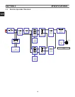
Page 16: ...3 0 16 section 3 SPECIFICATIONS 3 4 Machine Operation Flowchart...
Page 27: ...4 2 27 4 2 Control Transformer T2 0558007188 SECTION 4 DESCRIPTION OF OPERATION...
Page 30: ...4 3 30 4 3 Input Bridge 0558007068 0558007077 SECTION 4 DESCRIPTION OF OPERATION...
Page 35: ...4 6 35 blank...
Page 38: ...4 8 38 4 8 PCB1 Control Board 0558038317 SECTION 4 DESCRIPTION OF OPERATION 4 10 6 8 5 3 11 7...
Page 52: ...4 8 52 4 8 14 PCB1 Layout 0558038317 SECTION 4 DESCRIPTION OF OPERATION...
Page 60: ...4 10 60 4 10 2 Power PC Board Schematic 2 0558038315 SECTION 4 DESCRIPTION OF OPERATION 3 14 8...
Page 67: ...4 10 67 4 10 7 Power Board_PCB2 Control Relays 0558038315 SECTION 4 DESCRIPTION OF OPERATION...
Page 77: ...4 10 77 4 10 16 Buss Supply IGBT SECTION 4 DESCRIPTION OF OPERATION...
Page 91: ...4 11 91 4 11 Power Driver 0558038335 SECTION 4 DESCRIPTION OF OPERATION...
Page 109: ...4 19 109 SECTION 4 DESCRIPTION OF OPERATION 4 19 PT38 Plasma Torch...
Page 110: ...4 19 110 SECTION 4 DESCRIPTION OF OPERATION 4 19 PT38 Plasma Torch...
Page 113: ...5 0 113 5 1 Wiring Diagram 230 460 Volt 0558007543 section 5 WIring diagrams...
Page 114: ...5 0 114 5 1 Wiring Diagram 230 460 Volt 0558007543 section 5 WIring diagrams...
Page 115: ...5 0 115 5 1 Wiring Diagram 230 460 Volt 0558007543 section 5 WIring diagrams...
Page 116: ...5 0 116 section 5 WIring diagrams 5 1 Wiring Diagram 230 460 Volt 0558007543...
Page 117: ...5 0 117 section 5 WIring diagrams 5 1 Wiring Diagram 230 460 Volt 0558007543...
Page 118: ...5 0 118 5 2 Wiring Diagram 400 400V CE 0558007547 section 5 WIring diagrams...
Page 119: ...5 0 119 section 5 WIring diagrams 5 2 Wiring Diagram 400 400V CE 0558007547...
Page 120: ...5 0 120 5 2 Wiring Diagram 400 400V CE 0558007547 section 5 WIring diagrams...
Page 121: ...5 0 121 section 5 WIring diagrams 5 2 Wiring Diagram 400 400V CE 0558007547...
Page 122: ...5 0 122 5 2 Wiring Diagram 400 400V CE 0558007547 section 5 WIring diagrams...
Page 123: ...5 0 123 section 5 WIring diagrams 5 2 Wiring Diagram 400 400V CE 0558007547...
Page 124: ...124 5 3 Wiring Diagram 575V 0558007545 section 5 WIring diagrams...
Page 125: ...125 section 5 WIring diagrams 5 3 Wiring Diagram 575V 0558007545...
Page 126: ...126 5 3 Wiring Diagram 575V 0558007545 section 5 WIring diagrams...
Page 127: ...127 section 5 WIring diagrams 5 3 Wiring Diagram 575V 0558007545...
Page 128: ...128 5 3 Wiring Diagram 575V 0558007545 section 5 WIring diagrams...
Page 129: ...129 section 5 WIring diagrams 5 3 Wiring Diagram 575V 0558007545...
Page 130: ...130 blank...
Page 135: ...6 0 blank 135...
Page 136: ...6 0 136 section 6 replacement parts 6 3 Front 0558007540...
Page 140: ...6 0 140 6 3 Top 0558007540 section 6 replacement parts...
Page 144: ...6 0 144 section 6 replacement parts 6 3 Left Inside2 0558007540...
Page 146: ...6 0 146 section 6 replacement parts 6 3 Rear View 0558007540...
Page 148: ...6 0 148 6 3 Front Rear Isometric Views 0558007540 section 6 replacement parts...
Page 159: ...159 section 7 mechanized conversion 20 Trim all tie wraps and replace the unit s cover...
Page 166: ...10 166 SECTION 9 General information 10 3 Ohm s and Watt s Laws...
Page 171: ...10 171 10 6 Ohm Testing SECTION 9 General information...
Page 172: ...10 172 10 7 Diode Testing SECTION 9 General information...
Page 173: ...10 173 10 8 Ripple SECTION 9 General information...
Page 174: ...10 174 10 9 Voltage Measurement SECTION 9 General information...
Page 178: ...10 178 IGBT Tester Schematic 10 10 1 IGBT Testing SECTION 8 General information...
Page 182: ...182 revision history Original release 11 2008 1...


