


7
F.
FEEDING WIRE
1.
With MIG-41 Gun completely installed and all
power OFF, feed wire by hand through the feed
rolls of the wire feeder and guide the end of the
wire into the liner of the wire feeder connector as-
sembly. Then close the feed roll clamp.
2.
Pull the drive roll cap off gun and flip idler arm down.
Remove nozzle and contact tip from front end of
gun.
3.
Lay the gun and cable out straight and then inch
the wire through the cable. Inching can be accom-
plished from either the wire feeder or gun.
4.
When wire reaches the drive roll, make sure the
wire fits into the groove of the drive roll and is di-
rected into guide tube opening in the wire guide of
gun.
The drive roll components and wire are electrically
hot when gun trigger is depressed.
5.
When wire appears out of the front end of gun,
reassemble contact tip and nozzle. Close idler arm
and reinstall the drive roll cap .
Do not adjust the
pre-set tension in the cap knobs. Do not inch
the wire using the control inch button when
the wire is completely through the torch and
the idler arm closed. Birdnesting will occur at
the feeder.
IV. OPERATIONS
A. ADJUSTMENTS
1.
Before welding, ease tension on the wire feeder
feed rolls if necessary. (See appropriate wire feeder
instruction booklet.) They should not be tight
enough to shave the wire. Proper wire feeding re-
quires the pull motor of the gun and the push at
the wire feeder working together.
2.
Before welding, also be sure the torch gas system
has been thoroughly purged and the coolant sys-
tem has been completely filled.
Whenever welding above 250 amps, a No. 14 filter
lens should be worn on your protective helmet. Up
to 250 amps, use a No. 12 filter lens. Refer to page
2 of this booklet for additional operating precau-
tions.
CAUTION: Do not drop gun or remove spatter from
nozzle by hitting the front end against a
hard surface. This may damage the front
end and/or motor assembly. A damaged
front end can cause gas or coolant leak-
age.
V.
MAINTENANCE
If this equipment does not operate properly, stop
work immediately and investigate the cause of the
malfunction. Maintenance work must be performed
by an experienced person, and electrical work by
a trained electrician. Do not permit untrained per-
sons to inspect, clean, or repair this equipment.
Use only recommended genuine ESAB replace-
ments parts.
A. NOZZLES
Spatter can be removed from the inside of the nozzle
with a hand reamer or file. Adherence of spatter can
be minimized and removal made easier by coating the
inside of the nozzle with No. 65 Nozzle Anti-Spatter
Compound (4-oz. container - P/N 03N65; 1-qt. con-
tainer - P/N 08N75).
VI. REPLACEMENT PARTS
All replacement parts are keyed in Figs. 3, 4 and 5.
Order replacement parts by part number and part
name. Do not order by part number alone. Replace-
ment parts may be ordered from your welding prod-
ucts distributor or ESAB Welding & Cutting Systems,
Customer Service Dept., Florence, SC.
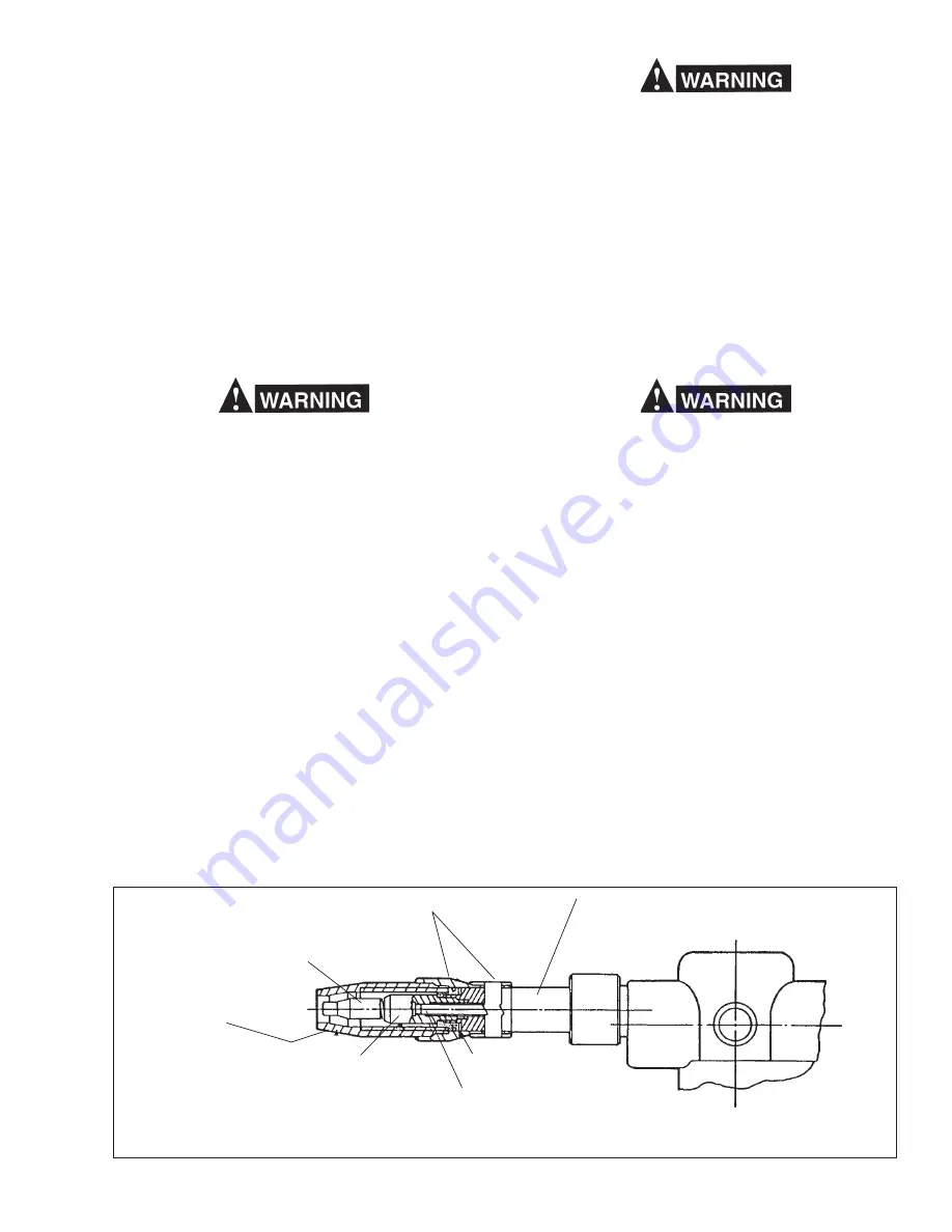
Fig. 3 - Replaceable Front End Parts
CONTACT TIP - See Table 3
NOZZLE - See Table 3
(No. 10 supplied with torch)
*TIP ADAPTOR - 18927
OPT. ACCY: 45° CURVED FRONT BODY - 19757
Requires: WIRE GUIDE - 19758
includes: LINER - 19759
FRONT BODY ASSY. - 19258
includes: NOZZLE BODY & CLAMP - 18930
INSULATOR ASSY. - 18924
INSULATOR ASSY. - 18924
(included w/19258)
WIRE GUIDE - 19991
LOCK NUT - 19264 (located in torch body
under drive roll cap)
NOZZLE BODY & CLAMP - 18930 *
(included w / 19258)
* Nozzle Body & Clamp replacement requires using Nozzle Body Replacement Tool Kit - 19092