


clka0p11
−
14
−
clka0de1
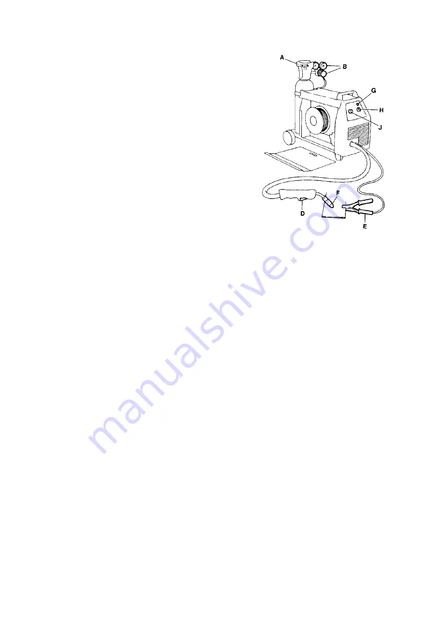
OPERATION
S
Connect the return current conductor clamp (E)
to the workpiece.
S
When welding with solid wire, open the gas valve (A) on
the gas bottle and adjust the gas flow by reducer valve (B).
The gas flow must be 8
−
12 litres per minute.
S
Turn on the power unit and set a suitable voltage
with knob (H).
S
Hold the welding torch trigger switch (D) pressed
until filler wire is fed out through the contact tip (F).
S
Select suitable welding data with the voltage cont-
rol selector (H) and the wire feed control knob (J),
as shown in the table on page 15.
S
Start welding. Adjust the settings if necessary.
S
The yellow LED (G) on the front panel will light if the thermal
overload cutout operates as a result of overload.
The overload cutout resets automatically when the machine has cooled to a safe tempera-
ture.
MAINTENANCE
S
Cleaning away dust
Blow the unit clean with compressed air at reduced pressure.
S
Wire feed mechanism
The wire feed mechanism should be cleaned, and wearing parts replaced, at regular inter-
vals in order to ensure smooth, reliable wire feed.
Do not tension the pressure roller too hard, as this will result in abnormal wear to the
pressure roller, the feed roller and the wire guide.
S
Welding torch
Blow the wire guide clean and clean the gas nozzle at regular intervals.
Summary of Contents for LKA 150
Page 1: ...0349 300 001 Valid for serial no 923 xxx xxxx 040928 LKA 150 clka0p00 Service manual ...
Page 7: ...clka0e01 5 clka0de1 CONNECTION DIAGRAM LKA 150 ...
Page 8: ...clka0e02 6 clka0de1 CIRCUIT DIAGRAM CIRCUIT BOARD AP1 ...
Page 11: ...clka0e02 9 clka0de1 CIRCUIT DIAGRAM CIRCUIT BOARD AP1 ...
Page 13: ... 11 clka0de1 LOAD CHARACTERISTIC LKA 150 clka0p06 ...
Page 17: ... 15 clka0de1 WELDING DATA SELECTION clka0p13 ...
Page 18: ......
Page 21: ...clka0p02 18 clka0se1 ...
Page 23: ...clka0p03 20 clka0se1 ...


