


19
2. Always commence with a last minute check for safety
and protection.
3. Check the tungsten electrode tip is correctly ground,
especially for DC applications, see Figure 4. To ob-
tain a stable arc the electrode should be ground as
shown. Use less sharp point for AC applications.
4. Adjust the tungsten electrode so that it extends be-
tween 5/32” - 1/4” beyond the end of the ceramic
cup.
Always disconnect the unit from the main supply
when changing tungsten electrodes or while convert-
ing between TIG and MMA applications.
4. Switch on at the electricity supply. Set the power on/
off switch to “ON”.
If MMA mode is selected open circuit voltage is
present at the output terminals as soon as the power
switch is set to on.
5. Ensure gas flow is correctly set, usually 6-9 I/min
(12-18 cu ft/hr).
6. Position the tungsten 3-5mm (1/8” - 3/16”) above the
work, warn bystanders to shield their eyes and lower
your weld hood.
7. If HF start mode has been selected, depress the torch
(foot) switch. The HF output will automatically strike
the arc without the need to touch the electrode to
the work.
8. If non-HF mode has been selected, press the torch
(foot) switch and lightly touch the tungsten tip to the
work and lift it off again to initiate the arc.
9. In the 4 stroke mode the torch switch can be released
once the arc has struck.
Note
In 4 stroke the arc will start at the start current
setting until the switch is released.
10. Release (press & release) the torch switch to down
slope the current and stop welding.
11. Maintain the torch in position over the weldpool while
the post gas purge is running.
3.2.1 MMA Welding Set-Up
IMPORTANT!
If a Foot Control is connected to the unit it must be
removed before attempting to use the unit for MMA
welding. Removing the Foot Control allows full cur-
rent control at the front panel!
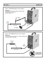
1. Connect the electrode holder lead to the
+
(Positive)
output connection.
2. Connect the work/workbench to the
-
(Negative)
output connection.
NOTE
Some MMA electrodes are recommended for use on
DC Electrode Negative polarity. If so reverse the con-
nections made in 1 and 2 above.
3. Set the polarity switch as required, DC or AC.
4. Set the welding current control to the required weld-
ing current value.
5. Set Start Current at 100% (maximum),
arc will not
transfer properly if this control is below 100%.
6. Set the process selector switch to MMA.
7. Fit the appropriate electrode in the holder.
SECTION 3
OPERATION
Summary of Contents for Heliarc 161
Page 4: ...4 TABLE OF CONTENTS ...
Page 22: ...22 SECTION 4 MAINTENANCE ...
Page 26: ...26 SECTION 6 REPLACEMENT PARTS 12 9 3 4 15 5 17 18 16 8 14 13 6 7 11 10 19 20 ...
Page 28: ...28 SECTION 6 REPLACEMENT PARTS ...
Page 29: ...29 Notes ...
Page 30: ...30 Notes ...


