15
2.3 + (Positive) Output Receptacle
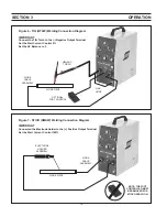
For TIG welding applications connect to the work using
a suitable work return lead and clamp. For MMA (stick)
welding this is usually the connection point for the elec-
trode holder (electrode po).
2.4 - (Negative) Output Receptacle
For TIG welding this is the power connection point for
the TIG torch. For MMA (stick) welding this is usually the
work connection.
Note:
The tig torch must ALWAYS be connected to the nega-
tive (-) terminal
2.5 Gas Outlet to Torch
Connect the TIG torch gas hose to this fitting.
2.6 Remote Control Socket (14 pin)
For connection of a remote control device like the FC-5B
foot control, TC-2B torch control or TC-3A Torch switch.
By depressing the foot pedal or thumb switch, the weld
current will increase or decrease within the range preset
on the power source current control potentiometer.
2.7 Power Switch
Setting the switch to “ON” energizes the internal circuitry.
The switch should be illuminated when set to the “ON”
position.
Dangerous voltages may still be present inside the
unit when the power switch is off. Always discon-
nect the unit from the main electricity supply before
accessing internal parts.
2.8 Process Mode Selector Switch
Four different TIG operating modes are provided as well
as MMA welding mode. The TIG modes are as follows:
A) 2 Stroke with HF (High Frequency) - The normal
method for TIG welding using non-contact arc
striking. Press the torch switch (or foot control)
to start the arc. Release the torch switch to ini-
tiate the down-slope and stop welding.
B) 4 Stroke with HF - For long duration welds the
torch switch can be electronically latched. Press
to initiate the TIG arc, the arc will strike and then
remain at the start current level while the switch
continues to be held. Releasing the switch al-
lows the current to slope up to the main current
setting.
Repressing the switch initiates the weld stop pro-
cedure. If the switch is repressed and then im-
mediately released the arc will go off immedi-
ately. Alternatively, repressing and holding the
switch permits the current to slope down to its
final level where it will remain until the switch is
finally released.
C) 2 Stroke “Touch Start” (Non HF) - When HF may
cause problems in surrounding sensitive equip-
ment, see HF Emission Prevention, touch start
TIG striking can be used. Press the switch and
touch the tungsten momentarily to the work to
initiate the arc. Release the switch to slope down
and stop welding.
D) 4 Stroke “Touch Start” (Non HF) - See B) above
but using scratch start TIG striking method as
described in c) above.
When MMA is selected open circuit voltage is
immediately available at the output terminals and
the HF and gas control circuitry are disabled.
2.9 Polarity Selector Switch
Selects either AC or DC polarity welding methods.
2.10 AC Balance Control
For AC TIG (& MMA) welding the control enables the
operator to adjust the “balance” of the AC current to
achieve either greater cleaning (more positive) or greater
penetration (more negative) of the workpiece. As the
control is rotated clockwise the balance of the AC wave
changes from more negative to more positive; clockwise
increases cleaning action in aluminum AC welding. This
control changes the AC wave balance from 91% straight
polarity (-) and 9% reverse po) to 64% straight
polarity and 34% reverse polarity (+).
2.11 Start Current
Enables the current at which the TIG arc is struck to be
preset. Useful when using small diameter tungstens. Start
current is set as a percentage of the main welding cur-
rent.
2.12 Welding Current
Sets the main welding current in the range 10 to 160A.
2.13 Slope Down Time
In order to allow the weld crater to fill-up before extin-
guishing the TIG arc, the current can be reduced slowly
to a lower background level before the arc is turned off.
This control sets the time for the down slope between 0-
10 seconds. Set it to minimum when using a remote foot
control unit.
SECTION 2
INSTALLATION
Summary of Contents for Heliarc 161
Page 4: ...4 TABLE OF CONTENTS ...
Page 22: ...22 SECTION 4 MAINTENANCE ...
Page 26: ...26 SECTION 6 REPLACEMENT PARTS 12 9 3 4 15 5 17 18 16 8 14 13 6 7 11 10 19 20 ...
Page 28: ...28 SECTION 6 REPLACEMENT PARTS ...
Page 29: ...29 Notes ...
Page 30: ...30 Notes ...


