background image

S0740 800 186/E080826/P50

-- 25 --

ct34_20

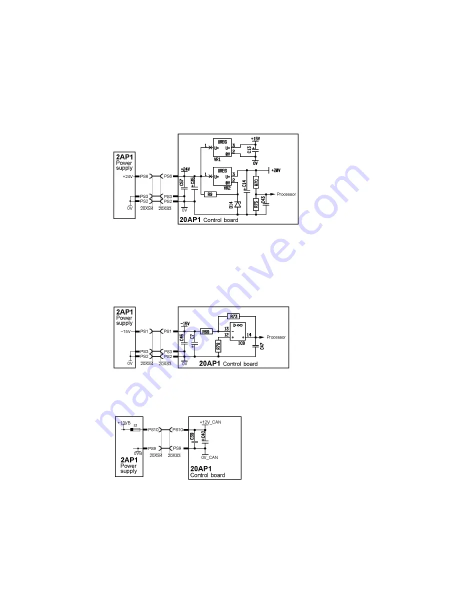
The voltage on terminal PS4 is normally about 24 V, when this drops below

20 V, pin 14 of IC6 goes low, providing the processor with a low power supply

voltage signal. The processor then stores current data and generates fault

code E4. When the 5 and 2.

5

V voltages are passing below their treshold

values, the processor receives a reset signal from IC16.
Fault code E4 is not displayed at normal power off

+15 V and +20 V

Voltage regulator VR2 produces an output voltage of +20

±

1.0 V, which

supplies the pulse width modulator output stage.
Voltage divider R70/R75 supplies 2.6 V to the processor. This provides a signal

that the power supply is available.
Voltage regulator VR1 produces an output voltage of +15 V, and this, together

with the --15 V supply, powers the analogue circuits.

--15 V

The --15 V power supply is monitored by the processor.

+12 V_CAN

The +13 VB from 2AP1 is used to supply the CAN circuits of the equipment.

This supply is referred to as + 12 V_CAN, its neutral point, 0 V_CAN, is

separated from the electronic neutral (0 V).

The tolerance of the voltage is 11.5 to 14.5 V.

Summary of Contents for Cadd Tig 1500i TA34

Page 1: ...0740 800 186 Valid for serial no 803 xxx xxxx to 843 xxx xxxx 080826 Caddyt Tig 1500i TA34 Tig 2200i TA33 TA34 Service manual...

Page 2: ...15AP2 Component positions 23 20AP1 Control board 24 20AP1 1 Power supply 24 20AP1 2 The CAN bus 26 Starting sequence 26 Communication interruptions 26 Terminating resistors 27 20AP1 3 Control panel i...

Page 3: ...ns without notice INSTRUCTIONS 45 SAFETY 45 INSTALLATION 45 Location 45 Mains power supply 45 OPERATION 46 Connections and control devices 46 Water connection 47 Overheating protection 47 MAINTENANCE...

Page 4: ...ts are located in the equipment The spare parts list is published as a separate document see page 48 This manual contains details of design changes that have been made up to and including August 2008...

Page 5: ...ltage 230V 10 1 50 60 Hz Primary current Imax TIG Imax MMA 13 8 A 21 3 A 24 9 A 24 1 A Mains supply Zmax 0 35 ohm Zmax 0 30 ohm No load power 30 W 30 W Setting range TIG MMA 3 150 A 4 150 A 3 220 A 4...

Page 6: ...ndoor and outdoor use Application class The symbol indicates that the power source is designed for use in areas with increased electrical hazard WIRING DIAGRAM The power source is based on a number of...

Page 7: ...orrector 15RS1 Shunt 60 mV at 100 A 15ST1 Thermal switch fitted in the winding of main transformer 15TM1 See page 28 15ST2 Thermal switch fitted on the heat sink See page 28 15TM1 Main transformer 20A...

Page 8: ...S0740 800 186 E080826 P50 8 ct34_00 Tig 1500i with control panel TA34...

Page 9: ...S0740 800 186 E080826 P50 9 ct34_00...

Page 10: ...S0740 800 186 E080826 P50 10 ct34_00 Tig 2200i with control panels TA33 and TA34...

Page 11: ...S0740 800 186 E080826 P50 11 ct34_00...

Page 12: ...MMC module consists of an operator s control panel and a display board The control panel is used for setting and displaying welding data The welding data are stored by the control board of the power s...

Page 13: ...i and 0487 631 880 is used for the Tig 2200i The difference between the two versions is the size of inductor L1 Circuit board 0487 631 880 is deliverd as spare part for all machines 2AP1 1 Interferenc...

Page 14: ...th high rupturing capacity Transistor Q5 is the switching element in a switched voltage supply The secondary voltage 24 V is sensed by IC2 and controlled by IC1 The isolation voltage of transformer T1...

Page 15: ...V The voltage is controlled by VR3 It has a tolerance of 0 25 V 15 V The voltage is controlled by VR2 It has a tolerance of 0 75 V 13 VB 12V CAN This voltage is unregulated It has a tolerance of 1 5...

Page 16: ...S0740 800 186 E080826 P50 16 ct34_02 2AP1 Component positions Power supply board 0487 064 884 used for the Tig 1500i WARNING Dangerous voltage mains voltage...

Page 17: ...S0740 800 186 E080826 P50 17 ct34_02 Power supply board 0487 631 880 used for the Tig 2200i and as spare part WARNING Dangerous voltage mains voltage...

Page 18: ...F transformer 10TV1 is about 550 V The secondary voltage is about 11 kV if a 4 metre long welding torch is connected If the welding torch is 16 metre long the HF spark is about 8 kV Due to electromagn...

Page 19: ...S0740 800 186 E080826 P50 19 ct33_10 10AP1 Component positions WARNING Dangerous voltage mains voltage...

Page 20: ...charging circuit the PFC circuit the gate circuits and the switching circuits The mains rectifier the switching transistors and parts of the charge and PFC circuits are integrated in a semiconductor...

Page 21: ...river transformer for galvanic isolation of the drive circuits from controller board 20AP1 Switching circuit The switching transistors are integrated in the semiconductor module PM1 Supply to 2AP1 The...

Page 22: ...ct33_15_1 15AP1 Component positions Pin positions of the semiconductor module Seen from the component side of the board Pin 1 marked P1 starts in the down left corner and continuous anticlockwise aro...

Page 23: ...the welding current from inductor 15L1 If the diode module has failed a replacement module must be fitted in accordance with the instructions on page 44 Inductor L1 forms an LC circuit with C3 C4 and...

Page 24: ...ne ID a hardware ID and a unit type number To read this you need the ESAT service kit see page 37 S The machine ID defines which type of power source the board is intended for S The hardware ID shows...

Page 25: ...Voltage regulator VR2 produces an output voltage of 20 1 0 V which supplies the pulse width modulator output stage Voltage divider R70 R75 supplies 2 6 V to the processor This provides a signal that...

Page 26: ...ply to the CAN circuits on 20AP1 Starting sequence On power up the board s CAN controller reads in the bus speed from the micro processor 400 kbit s The circuit board displays the starting sequence fr...

Page 27: ...s of the CAN bus must be terminated by resistive loads Principle diagram of the CAN bus and connecting up of the terminating resistors 20AP1 3 Control panel interface circuits See the service manual f...

Page 28: ...switches operates the power source is stopped fault code E06 is displayed The power source cannot be restarted until it has cooled sufficiently for the switch es to reclose 20AP1 6 Shunt and current...

Page 29: ...above 45 V are defined as no welding Output voltage is produced only when TIG welding is in progress If the open circuit voltage arc voltage is above 45 V for more than 100 milliseconds the open circu...

Page 30: ...al welding mode In the MMA normal welding mode the welding current is briefly increased at the start of welding The peak current phase 1 in the diagram above is engaged for 150 milliseconds The peak c...

Page 31: ...mp starts if the water lock microswitch is closed 3 Welding starts Stopping welding 1 The welder releases the trigger switch 2 Welding stops 3 The water pump continues to run for a further 6 5 minutes...

Page 32: ...am above The print number is NOT the same as the ordering number of the board Version 1 of 20AP1 Print numbers up to and including 487343 004 Power sources with serial no 803 xxx xxxx are delivered wi...

Page 33: ...ults are monitored detected in two ways by test routines that are run on initiation and by functions that can detect a fault when it occurs The control panel displays a unit number to indicate which u...

Page 34: ...ult persists load new software via ESAT If the fault still persists replace circuit board 20AP1 which carries the memory chip 2 Microprocessor RAM error The microprocessor is unable to read write from...

Page 35: ...isabled by this fault Action Check that all units are correct connected to the CAN bus See also section 20AP1 2 The CAN bus on pages 26 to 27 16 High open circuit voltage VRD The open circuit voltage...

Page 36: ...all such items so various means are used to drain off any static discharge from persons to prevent the risk of ESD damage This is done by simple devices wrist straps connected to ground and conductiv...

Page 37: ...For this a computer program called ESAT ESAB software administration tool is needed The PC is connected to the welding equipment by a cable connector and a CAN reader From the ESAT it is possible to...

Page 38: ...1 and thyristor TY1 in parallel measure the resistance of R31 It must be 12 ohm on some boards the resistance of R31 is 6 8 or 10 ohm which are also approved values 2 PM1 diode P1D measure between res...

Page 39: ...terminal L2 The forward voltage drop must be 0 3 to 0 5 V 7 PM1 transistor Q2 measure the resistance between source the positive of capacitor 15C1 and gate pin 19 of the module The resistance must be...

Page 40: ...are marked on the picture below 4 Bend out the circuit board so that it has no contact with the connections of the diode module 5 Use a multimeter in diode test position to measure the forward voltage...

Page 41: ...5 from terminal G on control board 20AP1 3 Connect the gate pulse test cable of the SST 3 to terminal G on control board 20AP1 Measuring connection for the gate pulses 4 Switch on the machine 5 Connec...

Page 42: ...04 red and yellow from circuit boards 2AP1 and 15AP1 see the circuit diagram below Disconnections prior to soft starting 2 Connect the 230 V AC input of the SST 3 to terminals B2 and B4 on circuit boa...

Page 43: ...10 Switch on the machine and set it to MMA mode 11 Check that the DC voltage across smoothing capacitor 15C1 is 22 24 V 12 Check that the DC voltage at the welding terminals is about 6 7 V 13 If all t...

Page 44: ...o a torque of 2 5 Nm and then further tighten them to 4 5 Nm 3 Tighten the screws that connect transformer 15TM1 and capacitor 15C1 to circuit board 15AP1 to a torque of 4 5 Nm CAUTION Incorrectly fit...

Page 45: ...ent drawn from the mains supply influence the power quality of the grid Therefore connection restrictions or requirements regarding the maximum permissible mains impedance or the required minimum supp...

Page 46: ...OPERATION General safety regulations for the handling of the equipment can be found in the instruction manual Read through before you start using the equipment Connections and control devices 1 Conne...

Page 47: ...ety plates to connect or carry out service maintenance or repair work on welding equipment Note All guarantee undertakings from the supplier cease to apply if the customer himself attempts any work in...

Page 48: ...ermal cut outs have tripped S Check the mains power supply fuses The thermal cut out trips frequently S Make sure that you are not exceeding the rated data for the welding power source i e that the un...

Page 49: ...S0740 800 186 E080826 P50 49 notes NOTES...

Page 50: ...92 22 ESAB international AB Gothenburg Tel 46 31 50 90 00 Fax 46 31 50 93 60 SWITZERLAND ESAB AG Dietikon Tel 41 1 741 25 25 Fax 41 1 740 30 55 North and South America ARGENTINA CONARCO Buenos Aires...

Reviews: