background image

- 7 -

bm44d1ea

CAUTION

This product is intended for industrial use. In a domestic environment this product may
cause radio interference. It is the user's responsibility to take adequate precautions.

WARNING

When welding in an environment with increased electrical danger, only power
sources intended for this environment may be used. These power sources are
marked with the symbol

5.1

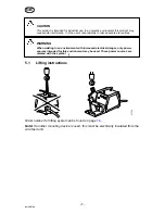
Lifting instructions

Order number for lifting eyelet can be found on page 

18

.

Note!

 If another mounting device is used, this must be electrically insulated from the

wire feed unit.

GB

Summary of Contents for Aristo Series

Page 1: ...GB Valid for serial no 613 xxx xxxx 0459 813 101 GB 110308 Aristo Origo Feed L3004 Instruction manual ...

Page 2: ...L DATA 6 5 INSTALLATION 6 5 1 Lifting instructions 7 6 OPERATION 8 6 1 Connections and control devices 9 6 2 Water connection 10 6 3 Wire feed pressure 10 6 4 Replacing and inserting wire 10 6 5 Changing feed rollers 10 7 MAINTENANCE 11 7 1 Inspection and cleaning 11 8 ORDERING SPARE PARTS 11 DIAGRAM 12 ORDERING NUMBER 14 WEAR PARTS 16 ACCESSORIES 18 ...

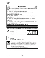
Page 3: ...ment may lead to hazardous situations which can result in in jury to the operator and damage to the equipment 1 Anyone who uses the equipment must be familiar with S its operation S location of emergency stops S its function S relevant safety precautions S welding and cutting 2 The operator must ensure that S no unauthorized person is stationed within the working area of the equipment when it is s...

Page 4: ...Protect bystanders with suitable screens or curtains FIRE HAZARD S Sparks spatter can cause fire Make sure therefore that there are no inflammable materials nearby NOISE Excessive noise can damage hearing S Protect your ears Use earmuffs or other hearing protection S Warn bystanders of the risk MALFUNCTION Call for expert assistance in the event of malfunction PROTECT YOURSELF AND OTHERS ESAB can ...

Page 5: ...the product can be found on page 18 3 1 Equipment The wire feed unit is supplied with S instruction manual for the wire feed unit S instruction manual in english for the control panel S decal with recommended wear parts Instruction manuals in other languages can be downloaded from the website www esab com 3 2 Control panel The units are supplied with one of the following control panels U6 With kno...

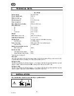
Page 6: ...at 60 duty cycle 365 A Enclosure class with sealed bobbin holder without sealed bobbin holder IP23 IP2X Accessories see page 18 Duty cycle The duty cycle refers to the time as a percentage of a ten minute period that you can weld or cut at a certain load without overloading The duty cycle is valid for 40 C Enclosure class The IP code indicates the enclosure class i e the degree of protection again...

Page 7: ...ate precautions WARNING When welding in an environment with increased electrical danger only power sources intended for this environment may be used These power sources are marked with the symbol 5 1 Lifting instructions Order number for lifting eyelet can be found on page 18 Note If another mounting device is used this must be electrically insulated from the wire feed unit GB ...

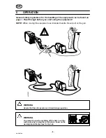
Page 8: ...ou start using the equipment NOTE When moving the equipment use intended handle Never pull on the gun AH 0935 WARNING Assure that the side panels are closed during operation WARNING To prevent the reel from sliding off the hub Lock the reel in place by turning the red knob as shown on the warning label attached next to the hub GB ...

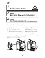
Page 9: ...ntrol devices 1 Control panel see separate instruction manual 6 Connection for welding current from power source OKC 2a 2b Connection for remote control unit Connection for U82 7 Connection for control cable from power source or cooling unit 3 Connection BLUE with ELP for coolant to the welding gun 8 Connection RED for coolant to cooling unit 4 Connection RED for coolant from welding gun 9 Connect...

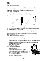
Page 10: ...ip If you hold the gun approx 50 mm from the piece of wood the wire should be fed out and bend fig 2 ÏÏ ÏÏ ÏÏ ÏÏ ÏÏ ÏÏ ÏÏ ÏÏ ÏÏ ÏÏ ÏÏ ÏÏ 6 4 Replacing and inserting wire S Open the side panel S Disconnect the pressure sensor by folding it backwards the pressure rollers slide up S Straighten out the new wire 10 20 cm File away burrs and sharp edges from the end of the wire before inserting it into ...

Page 11: ... is adjusted when delivered if readjustment is required follow the instructions below Adjust the brake hub so that wire is slightly slack when wire feed stops S Adjusting the braking torque S Turn the red handle to the locked position S Insert a screwdriver into the springs in the hub Turn the springs clockwise to reduce the braking torque Turn the springs counterclockwise to increase the braking ...

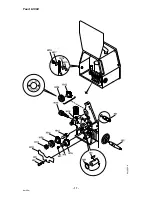
Page 12: ...Edition 110308 Diagram 12 bm44e ...

Page 13: ...Edition 110308 13 bm44e ...

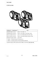
Page 14: ...ater cooling 0459 116 597 Wire feed unit Origot Feed L3004w MA23 with water cooling 0459 116 598 Wire feed unit Origot Feed L3004w MA23A with water cooling 0459 839 001 Spare parts list Feed L3004 0459 287 Instruction manual Control panel U6 0459 912 Instruction manual Control panel MA23 and MA23A Instruction manuals and the spare parts list are available on the Internet at www esab com ...

Page 15: ... 15 p ...

Page 16: ...U 0 8 A2 1 0 A2 0458 824 002 Feed pressure rollers Al Ø 1 0 1 2 mm U 1 0 A2 1 2 A2 0458 824 003 Feed pressure rollers Al Ø 1 2 mm U 1 2 A2 Use only pressure and feed rollers marked A2 R2 or S2 The rollers are marked with wire dimension in mm some are also marked with inch Item Ordering no Denomination Notes HI 6 Washer Ø 16 5x1 HI 7 Screw M4x12 HI 8 Screw M6x12 HI 9 Washer Ø 16 8 4x1 5 HI 10 0469 ...

Page 17: ...Feed L3004 17 bm44w ...

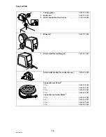
Page 18: ...cover metal Ø 300mm 0459 431 880 1 2 Bobbin holder Adapter for 5 kg bobbin 0458 704 880 0455 410 001 1 Adapter for 440 mm bobbin Note The wire feed unit must be placed on the floor when this adaptor i used 0459 233 880 1 2 Lifting eye Quick connector MarathonPact 0458 706 880 F102 440 880 ...

Page 19: ...880 1 Wheel kit 0458 707 880 1 Strain relief for welding gun 0457 341 881 Strain relief bracket for connection set 0459 234 880 Connection set 50mm2 1 7 m 5 m 10 m 15 m Connection set water 50mm2 1 7 m 5 m 10 m 15 m 0456 528 580 0456 528 581 0456 528 582 0456 528 583 0456 528 590 0456 528 591 0456 528 592 0456 528 593 ...

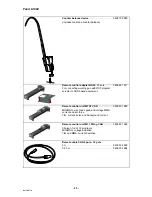
Page 20: ...r to CAN based equipment 0459 491 911 Remote control unit MTA1 CAN MIG MAG wire feed speed and voltage MMA current and arc force TIG current pulse and background current 0459 491 880 Remote control unit M1 10Prog CAN Choice of on of 10 programs MIG MAG voltage deviation TIG and MMA current deviation 0459 491 882 Remote cable CAN 4 pole 12 pole 5 m 0 25 m 0459 554 880 0459 554 884 ...

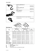
Page 21: ...880 0458 401 881 315A 60 285A 60 0 8 1 2 PSF 315 CLD 0468 410 885 0468 410 886 315A 60 285A 60 0 8 1 2 PSF 405 0458 401 882 0458 401 883 380A 60 325A 60 0 8 1 6 PSF 405 C 0458 499 882 0458 499 883 380A 60 325A 60 1 0 1 6 PSF 405 RS3 0458 401 892 0458 401 893 380A 60 325A 60 0 8 1 6 PSF 405 C RS3 0458 499 889 380A 60 325A 60 1 0 1 6 PSF 410 CW 0458 450 880 0458 450 881 380A 100 325A 100 0 8 1 6 PSF...

Page 22: ... 22 notes NOTES ...

Page 23: ... 23 notes NOTES ...

Page 24: ...21 7 44 88 87 41 SPAIN ESAB Ibérica S A Alcalá de Henares MADRID Tel 34 91 878 3600 Fax 34 91 802 3461 SWEDEN ESAB Sverige AB Gothenburg Tel 46 31 50 95 00 Fax 46 31 50 92 22 ESAB international AB Gothenburg Tel 46 31 50 90 00 Fax 46 31 50 93 60 SWITZERLAND ESAB AG Dietikon Tel 41 1 741 25 25 Fax 41 1 740 30 55 UKRAINE ESAB Ukraine LLC Kiev Tel 38 044 501 23 24 Fax 38 044 575 21 88 North and South...

Reviews: