SECTION 3 OPERATION
13
Power source solid state contactor becomes ener-
gized the moment the torch trigger is depressed.
Arcing can occur if the wire is brought to a ground.
Keep the torch away from ground until welding is to
begin
.
C. To start the weld, hold the torch so the welding wire
is approximately 1/4-in. from the work, then press
the torch trigger.
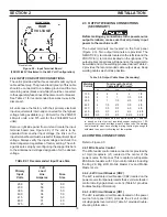
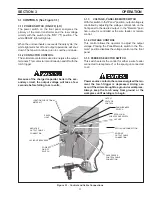
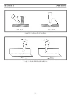
D. The welding wire should be pointed into the joint
at angles of approximately 45° for fillet welds, and
approximately 90° for butt welds, (Fig 3.2).
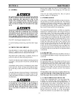
E. The torch angle relative to the length of the weld
should be approximately 10° from the vertical (Fig.
3.3).
F. When welding in the vertical position, traveling either
up or down, it is very important to keep the arc on the
leading edge of the puddle to ensure complete pen-
etration.
G. Some welders who are accustomed to welding with
stick electrodes may tend to push the torch into the
weld. This is neither necessary nor desirable, since
the wire electrode is being mechanically fed into the
weld.
H. To stop the weld, release the trigger and pull the torch
from the work. When leaving equipment unattended,
always shut OFF and disconnect all input power and
shut off shielding gas at source.
This equipment is provided with a thermostat in the
transformer windings which will open and prevent the
contactor from closing if the transformer windings are
overheated. If the thermostat opens, the ready light will
go out. Allow the equipment to idle with fan running until
the light comes back on before attempting to weld again.
b. Attempting to weld over grease or oil can cause
weld defects.
c. Before welding on aluminum, be sure to clean
surface thoroughly using a stainless steel brush.
3.2.3 SET-UP PROCEDURE
A. Determine the base plate material, wire type and
plate thickness to be welded.
B. Set VOLTAGE control and WIRE FEED speed con-
trol (ipm) on the wire feeder to the recommended
settings. If fine tuning is required while welding,
adjust the VOLTAGE control.
Only qualified personnel should make these changes.
Make certain the primary power has been discon-
nected and all safety procedures have been followed
before proceeding with these instructions.
3.2.4 WELDING OPERATION
A. Turn Power switch (on unit) to ON (I) position -- be
careful not to operate the torch switch.
NOTE: The 251cv features an automatic fan that ener-
gizes only to protect components from over-
heating. The fan will continue to run until the
components are cooled sufficiently.
B. Before starting the weld, the welding wire should
extend about 1/2-inch beyond the end of the nozzle.
Adjust this length by either clipping off the end of the
wire with insulated cutters or by using the torch
switch.


