SECTION 6 Troubleshooting
ESP 400C and 600C Plasma Power Sources
6-42
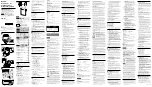
6.7 Wiring Diagrams – Drawing 5 – Part 1 400V 50H
z
(P/N 35879)
1 SH1(+) CLR(TP)
2 SH1(-) BLK(TP)
3 TB1-6 GRY
SH1-3 SHLD
1
2 TB8-4 ORN
3 TB8-3 BLK
4
5 K4-A YEL
6 TB9-14 WHT
PCB P3-3 WHT
7 FN3-4 ORN
8 FN3-3 GRY
1
2 K6-A BLU
3 PCB1 P2-6 WHT
PCB1 P6-2 WHT
1 TB7-7 WHT
2 TB1-6 GRY
3
4 TB8-5 VIO
5 TB8-6 YEL
1
2
3
4
5
6
7
8
9
10
11
12 TB11-2 YEL
13 TB11-4 YEL
14
GRY
GRY
GRY
GRY
VIO
VIO
VIO
VIO
VIO
PL4(+) GRY
PL5(+) VIO
1 TB9-1 RED
2 TB9-2 WHT
3 TB9-3 BRN
4 TB9-4 VIO
5 TB9-5 GRY
6 TB9-6 ORN
7 TB9-7 YEL
8 TB9-8 VIO
9 PRA1-BLK
10 T3-X1 BRN
11 TB9-24 YEL
T3-X4 GRN/YEL
12 T3-X7 RED
1 PCB2 P1-1 BLK
2 PCB2 P1-2 WHT
3 PCB2 P1-3 GRN
4 PCB2 P1-4 RED
5 PCB2 P1-9 GRY
6 PCB2 P1-10 VIO
7 PCB2 P1-5 BLU
8 PCB2 P1-6 ORN
9 PCB2 P1-7 YEL
10 PCB2 P1-8 BRN
11
12
1 TB7-9 ORN
2 PCB1 P3-3 WHT
3 TB9-11 GRY
4 TB9-10 BLU
5 TB9-9 BLK
6
1 S2-5 GRY
2 S2-2 VIO
3
4 T4-X1 BRN
5 T4-X4 GRN/YEL
6 T4-X7 RED
1 PCB3 P1-1 BLK
2 PCB3 P1-2 WHT
3 PCB3 P1-3 GRN
4 PCB3 P1-4 RED
5 PCB3 P1-9 GRY
6 PCB3 P1-10 VIO
7 PCB3 P1-5 BLU
8 PCB3 P1-6 ORN
9 PCB3 P1-7 YEL
10 PCB3 P1-8 BRN
11
12
1 TD1 P1-1 BLK
2 TD1 P1-3 GRN
3 TD1 P1-4 WHT
4 TD1 P1-2 RED
5 TD2 P1-1 BLK
6 TD2 P1-3 GRN
7 TD2 P1-4 WHT
8 TD2 P1-2 RED
9 PRA1- BLU
10 R51-1 GRY
11 R51-2 BLK
12 R51-3 VIO
13 S3-1 RED
14 S3-2 BRN
15 S3-3 WHT
TB9
P
CB4
P
1-9
ORN
P
CB1
P
5-1
RE
D
P
CB4
P
1-8
W
H
T
P
CB1
P
5-2
W
H
T
P
CB1
P
5-3
BRN
P
CB1
P
5-4
V
IO
P
CB1
P
5-5
GRY
P
CB1
P
5-6
ORN
PC
B
1 P
5-7
YEL
P
CB1
P
6-5
BL
K
P
CB1
P
6-4
BL
U
P
CB1
P
6-3
GRY
T
B
1-
12 W
H
T
P
CB1
P
2-8
W
H
T
T3
-H
2 WH
T
T
B
3-
2 W
H
T
K3
-B
W
H
T
K7
-B W
HT
TB
8-
17
WH
T
TB
3-
1 B
LK
T
B
1-
10
B
L
K
T
S
7-
1 B
L
K
P
L
3-
1 B
L
K
K3
-6
BL
K
K5
-6
BL
K
PC
B
1 P
5-1
1 YEL
PL
5(-) YEL
PL
4(-) YEL
K6
-B BL
K
T3
-H
1 B
LK
JU
M
PER
JU
M
PER
JU
M
PER
JU
M
PER
JU
M
PER
BLK
1
2
3
4
5
6
7
8
9
10
11
12
13
14
15
16
17
18
19
20
21
22
23
24
TB1-1 BRN
(LINE)
TB1-2 YEL
PCB1 P2-8 GRY
(LOAD)
PCB1 P2-7 ORN
FN3
1
2
3
4
PCB1 P5-10 BRN
PCB1 P5-11 GRN/YEL
PCB1 P5-12 RED
TB9-20 BLK
TB9-15 WHT
GR
Y
GRN
YEL
BL
U
T3
X1
X2
X3
X4
X5
X6
X7
TB1-7 BLK
(LINE)
TB1-8 WHT
CB1-2 BLK
(LOAD)
T2-X1 WHT
TB1-11 WHT
FN4
1
2
3
4
TB1-12 BLK
TB1-10 BLK
PCB1 P8-6 RED
PCB1 P8-5 GRN/YEL
PCB1 P8-4 BRN
BL
U
YEL
GRN
GR
Y
T4
H1
H2
X1
X2
X3
X4
X5
X6
X7
T4
GND5
P7
P6
P10
P11
P9
P8
P1
P2
P3
P4
P5
PCB1
T3
FN3
FN4
TB9
PL3-2 BRN
PCB4 P1-6 BLK
PCB4 P1-5 RED
J1-K VIO
J1-J GRY
PL1-2 WHT
PL2-2 WHT WHT
PL1-1 BLK
CB1-2 BLK
PL2-1 RED
J1-E RED
J1-G WHT
J1-F BLK
TB8-7 BLK
S2-6 GRY
S2-4 BLU
J1-D BLU
J1-C ORN
S2-1 ORN
R50-1 VIO
J1-B YEL
J1-A BRN
TS6-2 BRN
K7-A BRN
SH1(-) BLK(TP)
SH1(+) RED(TP)
T9-H2 WHT
T4-H2 BLK
TB9-14 WHT
C26-2 WHT
FN4-4 WHT
T4-H1 BLK
TB9-20 BLK
T9-H1 BLK
TB7-8 RED
TB8-8 RED
FN4-2 WHT
FN4-1 BLK
PCB1 P1-3 GRY
PCB1 P4-2 GRY
TB8-12 BLU
TB8-11 ORN
PCB1 P5-8 VIO
FN3-2 YEL
FN3-1 BRN
C45
C46
J1-H GRN
GND 5
18
17
16
15
14
13
12
11
10
9
8
7
6
5
4
3
2
1
TB1
P1
P2
P3
P4
P5
P6
P7
P8
P9
P10
P11
PCB1
TB1
VIEW H-H
Note: From ESP-400C/600C//400V,50 Hz
Drawing No. 0558002859, sheet 5 of 5
OR
Summary of Contents for 0558001729
Page 1: ...F 15 657 Jun 2005 Installation Operation and Maintenance for the ESP 400C Plasma Power Source...
Page 6: ...ESP 400C Plasma Power Source Table of Contents iv This page intentionally left blank...
Page 110: ...SECTION 7 Replacement Parts ESP 400C Plasma Power Source 7 10 7 7 Top View...
Page 112: ...SECTION 7 Replacement Parts ESP 400C Plasma Power Source 7 12 7 8 Back Inside View 2 1 4 2 3...