background image

WARNING

ARC WELDING AND CUTTING CAN BE INJURIOUS TO YOURSELF AND OTHERS. TAKE 
PRECAUTIONS WHEN WELDIN.  ASK FOR YOUR EMPLOYER’S SAFETY PRACTICES WHICH 
SHOULD BE BASED ON MANUFACTURERS’ HAZARD DATA.

ELECTRIC SHOCK – Can kill 

l

Install and earth the welding unitin accordance with applicable standards.

l

Do not touch live electrical parts or electrodes with bare skin, wet gloves or wet clothing.

l

Insulate yourself from earth and the workpiece.

l

Ensure your working stance is safe.

FUMES and GASES - Can be dangerous to health

l

Keep your head out of the fumes.

l

Use ventilation, extraction at the arc, or both, to take fumes and gases away from your breathing 
zone and the general area.

ARC RAYS - Can injure eyes and burn skin

l

Protect your eyes and body. Use the correct welding screen and filter lens and wear protective 
clothing.

l

Protect bystanders with suitable screens or curtains.

FIRE HAZARD

l

Sparks (spatter) can cause fire. Make sure therefore that there are no inflammable materials 
nearby.

NOISE - Excessive noise can damage hearing

l

Protect yours ears. Use earmuffs or other hearing protection.

l

Warn bystanders of the risk.

MALFUNCTIONS - Call for expert assistance in the event of malfunction

READ AND UNDERSTAND THE INSTRUCTION MANUAL BEFORE INSTALLING OR OPERATION.

PROTECT YOURSELF AND OTHERS!

ESAB can provide you with all necessary welding protection and accessories.

WARNING!

Read and understand the instruction manual before installing or operating.

Do not dispose of electrical equipment together with normal waste!

In observance of European Directive 2002/96/EC on Waste Electrical and Electronic 
Equipment and its implementation in accordance with national law, electrical equipment 
that has the end of its life must be collected separately and returned to an 
environmentally compatible recycling facility. As the owner of the equipment, you should 
get information on approved collection systems from our local representative. By 
applying this European Directive you will improve the environment and human health !

- 20 -

- 21 -

2        INTRODUCCION

™ 

The Origo Feed 302N P0 wire feeders are designed for semi-automatic MIG/MAG welding with solid wires, 
cored and aluminium in services of average and heavy production.

They have a wire feed mechanism of 2 feed rollers engaged and an electronic control system. They can be 
installed on the power source or on a wheel kit to move it around the workplace (optional). 

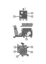
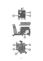
4.1) Front panel
1- Knob for setting wire feed speed.

2- Interruptor of manual wire release - Allows the wire to be fed without voltage in the welding gun.

3- Euro-conector for connect welding gun.

4.2) Side console

4- Wire feed mechanism.

4.3) Rear panel

5- Connection for welding current from power source.

6- Connection for control cable from power source.

7- Connection for shielding gas.

8- Brake hub.

9- Inlet nozzle.

3

TECHNICAL DATA

4

CONTROLS AND CONNECTORS

42 - 50/60

1,5 - 22,0

0,6 - 1,6

1,2 - 1,6

1,0 - 1,6

Euro-conector

Yes

Optional

230 x 570 x 380 (without bobbin cover)

230 x 570 x 455 (with bobbin cover)

10,8

Power supply (V - Hz)

Wire feed speed (m/mm)

Wire diameter (mm)

     Solid steel

     Cored wire

     Aluminium

Welding gun connection

Manual feeding of the wire

Bobbin cover

Dimensions (W x L x H) (mm)

Weight (kg)

Summary of Contents for 0402503

Page 1: ...agem MIG GMAW e arames tubulares FCAW Manual do Usu rio e pe as de reposi o Refer ncia OrigoFeed 302N P0 0402503 0216039 052014 V lido para n de s rie a partir de A10360033 A ESAB se reserva o direito...

Page 2: ...E CONECTORES 5 5 DIMENS ES 7 6 INSTALA O 7 7 OPERA O 9 8 MANUTEN O 9 9 DETEC O DE DEFEITOS 10 10 ADQUIRIR PE AS DE REPOSI O 10 11 CONJUNTO DE CABOS DE CONEX O 11 12 TOCHAS PARA SOLDAGEM 11 13 ACESS R...

Page 3: ...o equipamento l as medidas de precau o de seguran a pertinentes l o processo de soldagem ou corte 2 O operador deve certificar se de que l nenhuma pessoa n o autorizada se encontra dentro da rea de fu...

Page 4: ...cas fagulhas podem provocar inc ndios Por isso certifique se de que n o existem materiais inflam veis na rea onde est sendo realizada a soldagem ou corte RU DO O ru do excessivo pode provocar danos na...

Page 5: ...o manual do arame Permite alimentar o arame sem tens o na tocha de solda 4 2 Console lateral 4 Mecanismo de avan o do arame de 2 roldanas 4 3 Painel traseiro 5 Terminal para conex o da fonte de solda...

Page 6: ...6 1 2 3 8 9 4 6 7 5...

Page 7: ...fatores devem ser considerados ao se determinar o local de trabalho de uma m quina de soldar de maneira a proporcionar uma opera o segura e eficiente Uma ventila o adequada necess ria para a refrigera...

Page 8: ...arame Di metro mm 0900905 0900251 0901338 0900822 0900168 0901272 0712720 0900121 C digo 6 4 Ajuste da press o no arame Para determinar a correta press o de alimenta o do arame Certifique se de que o...

Page 9: ...mentadores de arame n o requerem qualquer servi o especial de manuten o apenas necess rio limp los internamente uma vez por m s com ar comprimido sob baixa press o seco e isento de leo Ap s a limpeza...

Page 10: ...prote o est de acordo com o arame utilizado flui pelo bocal da tocha e se a vaz o est correta Verificar se a velocidade do arame a tens o ajustada na fonte de soldagem est o corretamente ajustados Tab...

Page 11: ...0400822 0400823 12 TOCHAS PARA SOLDAGEM Obs Os conjuntos de cabos s o compostos de 01 Cabo de comando 01 Cabo de energia 01 Mangueira 01 Cabo Obra MODELOS MXL 200 MXL 270 MXL 340 MXL 400 MXL 400 AL M...

Page 12: ...12 13 ACESS RIOS Descri o C digo Kit Flux metro Origo Feed 302N 304N Kit Carrinho 0402770 0403692 Capa para Prote o do arame 0403700...

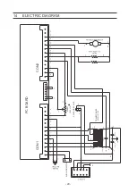
Page 13: ...22 1uFx400V 4 6 18 7 CON1 2 1 1 2 3 5 4 6 7 8 9 10 100 K LIN POT VELOCIDADE VALV SOLEN IDE 81 16 11 20 11 12 13 15 14 16 PLACA ELETR NICA MOTOREDUTOR 24V RLIM 2 X 4R7 X 25W 240 19 23 24 19 18 20 21A 2...

Page 14: ...da garantia viola o de qualquer uma das instru es e ou recomenda es contidas no Manual do Usu rio e ou neste termo Qualquer equipamento ESAB parte ou componente que tenha sido alterado submetido a uso...

Page 15: ...15 p gina em branco...

Page 16: ...16 p gina em branco...

Page 17: ...red wires FCAW Origo Feed 302N P0 User manual and spare parts P N OrigoFeed 302N P0 0402503 0216039 052014 From serial number A10360033 ESAB has the right to change technical characteristics of their...

Page 18: ...DATA 20 4 CONTROLS AND CONECTORS 20 5 DIMENSIONS 23 6 INSTALATION 23 7 OPERATION 25 8 MAINTENANCE 25 9 FAULTING TRACING 26 10 ORDERING SPARE PARTS 26 11 SET OF CABLES 27 12 WELDING GUNS 27 13 ACCESSOR...

Page 19: ...ipment must be familiar with l its operation l location of emergency stops l its function l relevant safety precautions l welding 2 The operator must ensure that l no unauthorized person is stationed...

Page 20: ...cause fire Make sure therefore that there are no inflammable materials nearby NOISE Excessive noise can damage hearing l Protect yours ears Use earmuffs or other hearing protection l Warn bystanders...

Page 21: ...wire to be fed without voltage in the welding gun 3 Euro conector for connect welding gun 4 2 Side console 4 Wire feed mechanism 4 3 Rear panel 5 Connection for welding current from power source 6 Con...

Page 22: ...22 1 2 3 8 9 4 6 7 5...

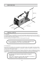
Page 23: ...n is needed for the refrigeration of the equipment and for the operator s safety The installation of any filter dispositive in the environment restricts the air volume availabe for the machine refrige...

Page 24: ...Aluminiun Cored 0 60 0 80 0 80 1 00 1 00 1 20 1 20 1 60 1 00 1 20 1 20 1 60 1 20 1 20 1 20 1 60 Type Diameter mm 0900905 0900251 0901338 0900822 0900168 0901272 0712720 0900121 P N 6 4 Wire feed press...

Page 25: ...NCE 8 1 Recomendations The wire feeder requires little maintenance in normal environment and opperation conditions It is sufficient to blow it dry clean using dry compressed air free from oil once a m...

Page 26: ...rch nozzle and the flow is correct Verify that the speed of the wire and the voltage set in powersource are properly adjusted Table 9 1 9 FAULTING TRACING 26 10 ORDERING SPARE PARTS The maintenance sh...

Page 27: ...Set of cables 25 meters 550 A Note The set of cable comprise of 01 control cable 01 power cable 01 hose 01 work cable MODELS MXL 200 MXL 270 MXL 340 MXL 400 MXL 400 AL MXL 500 MXL 501 D P N 0905980 0...

Page 28: ...28 13 ACCESSORIES Description P N Flowmeter Kit Origo Feed 302N 304N Wheel Kit Origo Feed 0402770 0403692 Wire protector 0407300...

Page 29: ...21A 42V 3 22 1uFx400V 4 6 18 7 CON1 2 1 1 2 3 5 4 6 7 8 9 10 100 K LIN SPEED SOLENOIDE VALVE 81 16 11 20 11 12 13 15 14 16 PC BOARD MOTOREDUCTOR 24V RLIM 2 X 4R7 X 25W 240 19 23 24 19 18 20 21A 22 23...

Page 30: ...elding or cut torch nipples torches and their components which are worn out by normal use of the equipment or any other damage caused by lack of preventive maintenance are not covered by this warranty...

Page 31: ...31 white page...

Page 32: ...32 white page...

Page 33: ...MIG GMAW e alambres tubulares FCAW ES Ref OrigoFeed 302N P0 0402503 Manual del usuario y repuestos 0216039 052014 V lido para n mero de serie desde A10360033 ESAB se reserva el derecho de alterar las...

Page 34: ...ROLES Y CONECTORES 37 5 DIMENSIONES 39 6 INSTALACI N 39 7 OPERACI N 41 8 MANTENIMIENTO 41 9 DETECCI N DE DEFECTOS 42 10 ADQUIRIR REPUESTOS 42 11 CONJUNTOS DE CABLES 43 12 ANTORCHAS PARA SOLDADURA 43 1...

Page 35: ...funcionamiento l Las medidas de precauci n y seguridad pertinentes l El proceso de soldadura 2 El operador debe cerciorarse de que l Nadie que no est autorizado se encuentre dentro del rea de funciona...

Page 36: ...spas pueden provocar incendios Por eso cerci rese de que no existan materiales inflamables en el rea en que se realiza la soldadura RUIDO El ruido excesivo puede provocar da os en el o do l Proteja su...

Page 37: ...Euroconector para instalar la antorcha de soldar 4 2 Consola lateral 4 Mecanismo de avance de alambre 4 3 Tablero posterior 5 Terminal para conectar la fuente de soldar 6 Enchufe para conectar el cabl...

Page 38: ...38 1 2 3 8 9 4 6 7 5...

Page 39: ...uada para refrigerar el equipo y para la seguridad del operador y el rea debe mantenerse limpia La instalaci n de dispositivos de filtro de aire ambiente restringe el volumen de aire disponible para l...

Page 40: ...0 1 20 1 20 1 60 1 20 1 20 1 20 1 60 0900905 0900251 0901338 0900822 0900168 0901272 0712720 0900121 C digo Tabla 6 1 6 4 Presi n en el alambre Para determinar la correcta presi n de alimentaci n del...

Page 41: ...de mantenimiento S lo es necesario limpiarlos internamente una vez por mes con aire comprimido a baja presi n seco y exento de aceites Finalizada la limpieza con aire comprimido verifique el ajuste de...

Page 42: ...gas de protecci n est de acuerdo con el alambre utilizado fluye por la boquilla de la antorcha y si el flujo est correcto Verifique si la velocidad del alambre y la tensi n de la fuente est n correct...

Page 43: ...ros 550 A Conjunto de cables 25 metros 550 A Obs Los conjuntos de cables se componen de 01 Cable de comando 01 Cable de energia 01 Manguera 01 Cable Masa MODELOS MXL 200 MXL 270 MXL 340 MXL 400 MXL 40...

Page 44: ...44 13 ACCESORIOS Descripci n C digo Kit Fluxometro Origo Feed 302N 304N Kit Carrito 0402770 0403692 Protector del alambre 0403700...

Page 45: ...2 1uFx400V 4 6 18 7 CON1 2 1 1 2 3 5 4 6 7 8 9 10 100 K LIN POT VELOCIDADE VALV SOLENOIDE 81 16 11 20 11 12 13 15 14 16 PLACA ELECTR NICA MOTOREDUCTOR 42V RLIM 2 X 4R7 X 25W 240 19 23 24 19 18 20 21A...

Page 46: ...ando con da os porta electrodos o pinzas de masa boquilla de torcha pistola de soldadura o corte torchas y sus componentes sujetos a desgaste o deterioro por el uso normal del equipo o cualquier otro...

Page 47: ...r verde Suporte do rolo de arame Lateral direita Potenci metro Bot o Interruptor P de epoxy Etiqueta do painel frontal Lateral esquerda Handler Brake hub Green display Wire support Right side Potentio...

Page 48: ...van o de arame Fecho Suporte do mec de avan o Man pulo vermelho Motoredutor Escovas para motor Nylon isolator Current cable Wire feed mechanism Locket Wire feed mechanism support Red handle Motoreduct...

Page 49: ...Isolante do resistor Placa eletr nica Suporte da placa V lvula solen ide Transformador Chicote el trico Gabinete Chapa intermedi ria Resistor Isolator for resistor PC Board PC board support Solenoid...

Page 50: ...05227 0905751 0905752 Description Isolador Base da tomada Tomada Guia de entrada Isolante com rebaixo Isolante sem rebaixo Isolator Outlet chasi Outlet Inlet nozzle Isolator with fillister Isolator wi...

Page 51: ...pa de prote o Parafuso de trava Parafuso da roldana Parafuso M3 x 25 Pino do suporte Dispositivo de press o Guia de entrada Mola Roldana de tra o Arm Pin Pressure feed roller Gear Shaft pressure arm N...

Page 52: ...ldagem These parts are subject to wear in normal operation conditions and should be substitued whenever they present any wear which interferes with the correct feeding of the welding wire Estos repues...

Page 53: ...53 P gina en blanco...

Page 54: ...54 P gina en blanco...

Page 55: ...55 P gina en blanco...

Page 56: ...uporte t cnico equipamentos 0800 701 3383 ESAB Suporte t cnico consumiveis 0800 701 3343 faleconosco esab com br AM RICA LATINA ESAB Centroamerica S A Ave Ricardo J Alfaro The Century Tower Piso 16 Of...

Reviews: