10.1 ELECTRONIC BOARD SIZE AND VOLTAGE SETTINGS
Page 1: ...ual activation of every single output from keyboard B1b Select Number of outputs B2x Activation time from 0 05 to 5 00 sec B3x Interval time from 1 to 999 sec B8a Short circuit protection of every single output B9b Electric control of output activation C0 Input activation from external contacts C4c Cleaning cycle C6a ON OFF cleaning cycle from external pressure switch STOP at the end of the cycle ...
Page 2: ... alarm description Press key E to reset alarm condition ATTENTION this function will be active only if the automatic selection of the load in set up is not selected The alarm switch on after 5 consecutive fails on the same output C0 Input activation from external contacts In Set up you can activate or deactivate the control of all the inputs of the device If inputs are deactivated they are conside...
Page 3: ...s from external contact active See Setup 5 1 G1 Maximum load power 25W per output HVA Input voltage selection By some jumpers on the board it is possible to change the supply voltage See label on the device pr board layout The ouput voltage for the electrovalves BUS line is fixed 24VDC JP1 Supply voltage selection between 115VAC or 230VAC SL Multi language display In Set up it is possible to selec...
Page 4: ... the device and remove it if it is present by using wet cloth 3 9 For supply voltages cabling and voltages applicable to the relay contacts follow the current rules 3 10 For all input control signals to the Timer D1a D5 D6 use anti flame wires with a minimum section of 0 5 mm 3 11 For the electrical connection of the supply voltage and filter cleaning electrovalves use anti flame wires with a mini...
Page 5: ...1 to 999 sec 001 999 B3x 5 sec 05 POSTCL INT B3c 005 sec Interval time between ev during post cleaning from 1 to 999 sec 001 999 B3c 5 sec 06 POST CYCLES D1x 002 cycles Number additional cycles after fan stop 00 99 D1x 5 07 ELECTROVAL N B1b 016 ev Selection Number of electrovalves B1a 08 EV TEST B10b 001 OFF TEST Manual activation of every single ev from keyboard B10 09 HOURS COUNTER D14a 00000 Ho...
Page 6: ...TILATOR STOP Cycle stops waiting for fan start or dP under set fan threshold See SET 11 section 5 1 D1x ACTIVAT EV 003 Activation output solenoid valve 3 WAITING 005 sec Waiting time before activation of the next ev CYCLE STOP FOR dP LOW Cycle stopped due to lack consensus C6A Contact C6a D6a open See 2 2 C6a POSTCLEANING ACT Additional cycles after fan stop active D1x Keypad lock Option on reques...
Page 7: ...D ELECTROVALVE 003 Overload alarm solenoid valves 3 B8b E2 ACT FAILED ELECTROVALVE 003 Solenoid valve not activated Solenoid valves 03 option on request B9x B6x 8 1 INFORMATION AND GUIDE ON THE DISPLAY 8 1 INFORMATION AND GUIDE ON THE DISPLAY Not available for this model ...
Page 8: ...9 1 WIRING DIAGRAM ...
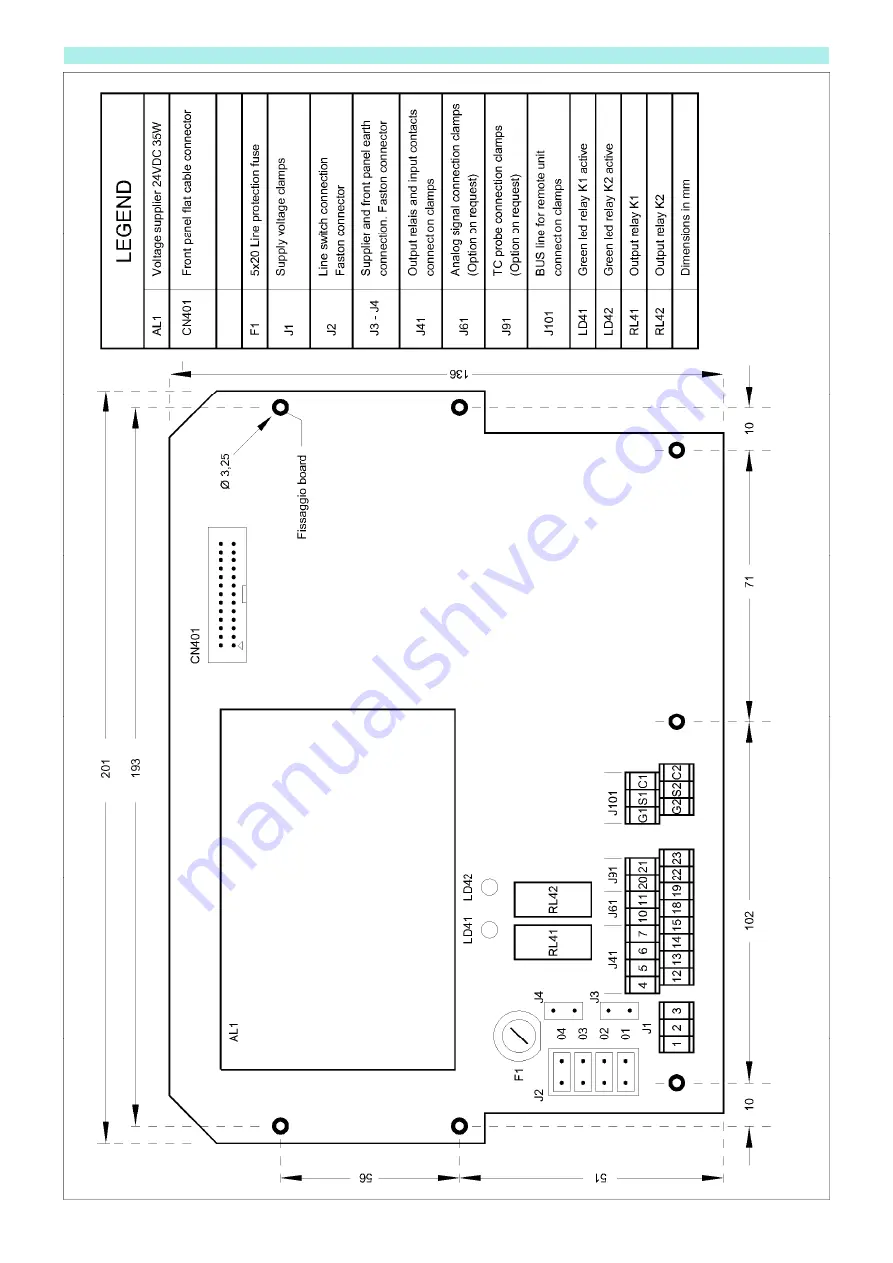
Page 9: ...10 1 ELECTRONIC BOARD SIZE AND VOLTAGE SETTINGS ...
Page 10: ...11 1 ENCLOSURE DIMENSIONS ...
Page 11: ...he microprocessor could be modified by external factor Switch Off the supply voltage of the sequencer Hold down key A and switch on the supply voltage By means of this operation the default data are loaded in set up Adjust the zero dP reading and the other parameters according to the filter s needs 13 1 WARRANTY The warranty lasts 4 years The company will replace any defective electronic component...
Page 12: ...escribed above is in conformity with the relevant Union harmonisation legislation The object of the declaration described above is in conformity with the relevant Union harmonisation legislation Directives 2014 30 UE 2014 34 UE and 2011 65 UE Directives 2014 30 UE 2014 34 UE and 2011 65 UE The following harmonised standards and technical specifications have been applied The following harmonised st...
Page 13: ... by the final user The company does not assume any responsibility Use only cable glands IP65 ATEX certified with same or superior certification of the device and type ISO R 68 The fixing holes must be done with the right diameter indicated for that cable gland With the purpose to avoid the entry of dust inside the equipment through the pneumatic connections for the reading of the dP insert on such...