background image


            User’s Manual – Orion DX 832IR 

© 2019 Ernitec. All rights reserved 

www.ernitec.com 

V 01280219 

2.1 

Power Connection 

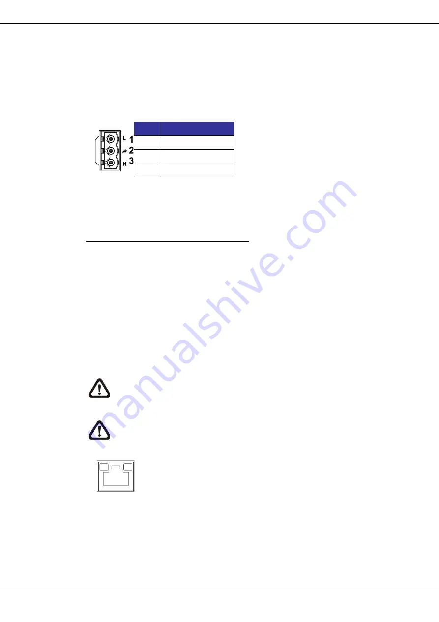
To power up the camera, connect the DC12V or AC24V power adaptor to the 
power connector of the camera and the power outlet. Refer to the diagram and 
pin definition below for AC24V power connection. 


Pin 

Definition 

AC24V L 

GND 

AC24V N 


Alternatively, users can use an Ethernet cable and connect it to the RJ-45 port 
of the camera and an UPoE 60W switch. 
 

Zero Downtime Power Switching (ZDT) 

When users connect DC12V power jack and the RJ-45 port at the same time, 
the power input comes from the DC12V connector. If the DC12V power source 
fails, the camera will switch power input seamlessly to the RJ-45 port until the 
DC12V power source is restored. 


2.2 

Ethernet Cable Connection 

To


connect one end of the Ethernet cable to the RJ-45 connector of the camera, 

and plug the other end of the cable to the network switch or PC. 
 

NOTE:

 In some cases, Ethernet crossover cable might be needed when 

connecting the camera directly to the PC. 


NOTE:

  Check the status of both power and network activity indicator 

LEDs. If either LED is unlit, please check the corresponding connection. 


Green Power LED lights up when the camera is powered up. 
Orange Network LED (1) flashes when data is being transmitted 

over network, (2) lights up for good network connection.   


Summary of Contents for Orion DX 832 IR

Page 1: ...User s Manual Orion DX 832 IR...

Page 2: ...may damage the unit as well as cause fire or an electric shock When cleaning is necessary shut down the system and unplug the unit from the outlet before uncovering the top cover Do not use liquid cle...

Page 3: ...e environment and human health which could otherwise be caused if this product is thrown into the garbage bin The recycling of materials will help to conserve natural resources For more details inform...

Page 4: ...3 Dimensions 6 1 4 Connectors 7 2 Camera Cabling 8 2 1 Power Connection 9 2 2 Ethernet Cable Connection 9 2 3 Audio AIarm I O RS 485 Connection 10 3 System Requirements 11 4 Access Camera 12 5 Setup...

Page 5: ...toring region is fully secured IP66 International standard is also guaranteed for outdoor installation Furthermore combining 0 downtime power switching ZDT technology the camera ensures smooth streami...

Page 6: ...IR PTZ Camera Quick Guide M4 Security Screw with Rubber 2 Pin Power Terminal Block DC12V Use 3 Pin Power Terminal Block AC 24V Use 14 Pin Alarm Audio I O Terminal Block NOTE To use an external power s...

Page 7: ...6 2019 Ernitec All rights reserved www ernitec com V 01280219 User s Manual Orion DX 832IR 1 3 Dimensions...

Page 8: ...r tool for at least 20 seconds to restore the system 5 Audio Alarm I O RS 485 Connector Audio Alarm I O RS 485 connection 6 BNC For analog video output 7 SD Card Slot Insert the SD card into the card...

Page 9: ...he installation should conform to all local codes Place all cables and the adaptor in dry and well waterproofed environments e g waterproof boxes The purpose is to prevent moisture accumulation inside...

Page 10: ...the power input comes from the DC12V connector If the DC12V power source fails the camera will switch power input seamlessly to the RJ 45 port until the DC12V power source is restored 2 2 Ethernet Ca...

Page 11: ...gram and pin definition tables below for audio alarm I O RS 485 connection Pin Definition Pin Definition Pin Definition Pin Definition 1 Audio Out 5 Alarm Out B1 9 Alarm In 4 13 GND Alarm I O RS 485 2...

Page 12: ...puter Minimum 1 Intel CoreTM i5 2430M 2 4 GHz 2 4 GB RAM Recommended 1 Intel CoreTM i7 870 2 93 GHz 2 8 GB RAM Operating System Windows 7 or later operating system Web Browser Microsoft Internet Explo...

Page 13: ...e camera is 192 168 0 250 Step 4 The default IP address of the camera may not be in the same LAN as the IP address of the PC If so the IP address of the camera needs to be changed Right click on the c...

Page 14: ...n t allow Viewer installation please check the Internet security settings or ActiveX controls and plug ins settings refer to section Setup Internet Security to continue the process The Information Bar...

Page 15: ...ll be shown as the figure below Zoom and Focus Adjustment The live image will be displayed on the Home page when the camera is successfully accessed If zoom or focus is not at the desired position ple...

Page 16: ...d under Streaming Video Configuration The default value of the video resolution is as below 2M Normal Mode H 265 1920 x 1080 30 25 fps H 265 1920 x 1080 30 25 fps HDR Mode 3M Normal Mode H 265 2048 x...

Page 17: ...tion and retrieve data by uploading an existing configuration file to the camera It is especially convenient to make multiple cameras having the same configuration Export Users can save the system set...

Page 18: ...ndows Start Menu activate Control Panel and then double click on Add or Remove Programs In the Currently installed programs list select Ernitec Viewer and click on the button Remove to uninstall the e...

Page 19: ...Security Settings window will pop up Step 3 Under ActiveX controls and plug ins set ALL items as listed below to Enable or Prompt Please note that the items vary by IE version ActiveX controls and plu...

Reviews: