background image

Network Video Recorder Quick Start Guide 

13 

1.


Enter the Shutdown menu.


Menu > Shutdown 


Figure 2. 2


Shutdown 


2.


Select the 

Shutdown

 button. 

3.


Click the 

Yes

 button. 

4.


Turn off the power switch on the rear panel when the attention pops up. 


Figure 2. 3


Power off 


2.3


Activating Your Device     

Purpose: 

For the first-time access, you need to activate the device by setting an admin password. No operation is allowed 

before activation. You can also activate the device via Web Browser, SADP or client software. 

Steps: 

1.


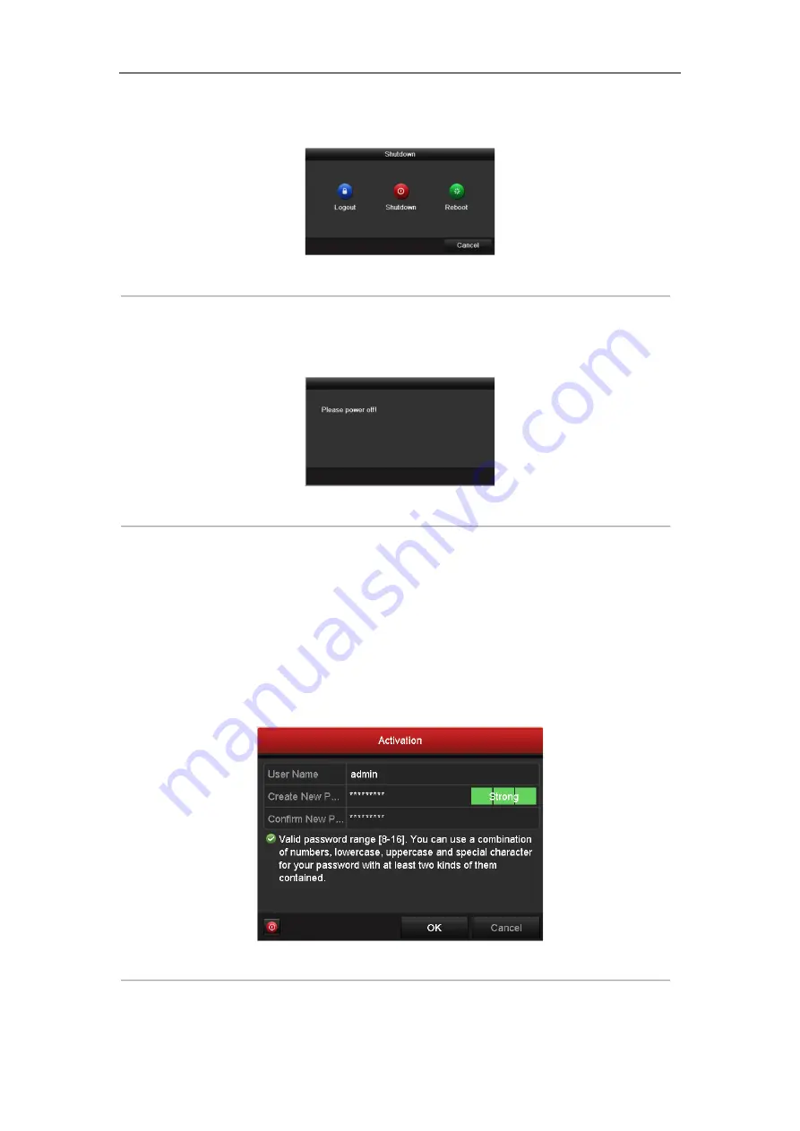
Input the same password in the text field of

 Create New Password

 and 

Confirm New Password


Figure 2. 4


Set Admin Password 


Summary of Contents for MicroView MVINVR-08POEHP-E

Page 1: ...Network Video Recorde Quick Start Guide MVINVR 08POEHP E...

Page 2: ...of Alarm Output 9 Connection of Alarm Connectors 10 2 4 HDD Storage Calculation Chart 11 Chapter 3Menu Operation 12 3 1 Menu Structure 12 3 2 Startup and Shutdown 12 3 3 Activating Your Device 13 3 4...

Page 3: ...esponsible for compliance could void the user s authority to operate the equipment FCC compliance This equipment has been tested and found to comply with the limits for a Class A digital device pursua...

Page 4: ...60950 1 standard Please refer to technical specifications for detailed information Do not connect several devices to one power adapter as adapter overload may cause over heating or a fire hazard Pleas...

Page 5: ...ditional information to emphasize or supplement important points of the main text Chapter1 Description of Panels 1 1 Front Panel MVINVR 08POEHP E Table 1 1 Description of Front Panel No Name Descripti...

Page 6: ...or the cameras and to provide power over Ethernet Installation and Connections 1 3 NVR Installation During installation of the NVR 1 Use brackets for rack mounting 2 Ensure ample room for audio and vi...

Page 7: ...he HDD in the HDD rack using the provided screws Fasten the screws on the button to fix the HDD Figure 1 3 Install the HDD 3 Connect one end of the data cable to the NVR motherboard and the other end...

Page 8: ...asten screws Steps for other models 1 Remove the cover from the NVR by unfastening the screws on the rear and side panel Figure 1 6 Remove the Cover 2 Connect one end of the data cable to the motherbo...

Page 9: ...Guide 8 Figure 1 8 Connect the power cable 4 Place the HDD on the bottom of the device and then fasten the screws on the bottom to fix the HDD Figure 1 9 Place the HDD on the bottom 5 Re install the...

Page 10: ...the device Figure 1 10 Alarm Input Wiring Wiring of Alarm Output To connect to an alarm output AC or DC load use the following diagram Figure 1 11 Alarm Output Wiring For DC load the jumpers can be us...

Page 11: ...JP 3 jumper Connection of Alarm Connectors To connect alarm devices to the NVR 1 Disconnect pluggable block from the ALARM IN ALARM OUT terminal block 2 Unfasten stop screws from the pluggable block i...

Page 12: ...ate Storage Used 96K 42M 128K 56M 160K 70M 192K 84M 224K 98M 256K 112M 320K 140M 384K 168M 448K 196M 512K 225M 640K 281M 768K 337M 896K 393M 1024K 450M 1280K 562M 1536K 675M 1792K 787M 2048K 900M 4096...

Page 13: ...structure may vary according to different models 2 2 Startup and Shutdown Proper startup and shutdown procedures are crucial to expanding the life of the NVR To start your NVR Steps 1 Check the power...

Page 14: ...the attention pops up Figure 2 3 Power off 2 3 Activating Your Device Purpose For the first time access you need to activate the device by setting an admin password No operation is allowed before acti...

Page 15: ...can better protect your product 2 Click OK to save the password and activate the device For the old version device if you upgrade it to the new version the following dialog box will pop up once the de...

Page 16: ...an use the configured unlock pattern for future login Figure 2 7 Draw the Unlock Pattern 2 5 Login and Logout User Login Purpose If NVR has logged out you must login the device before operating the me...

Page 17: ...enu operation on the screen is invalid It is required to input a user name and password to unlock the system 2 6 Using the Setup Wizard The Setup Wizard can walk you through some important settings of...

Page 18: ...hernet interface for other models 2 Select the General tab 3 In the General Settings interface you can configure the following settings NIC Type IPv4 Address IPv4 Gateway MTU and DNS Server If the DHC...

Page 19: ...lly Or you can choose to custom add the IP camera by editing the parameters in the corresponding text field and then click the Add button to add it 2 9 Live View Icons are provided on screen in Live V...

Page 20: ...on Detection Record on your demand Figure 2 13 Start Recording from Right click Menu 2 Click the Yes button in the pop up Attention message box to confirm the settings All the channels will start to r...

Page 21: ...Network Video Recorder Quick Start Guide 20 Figure 2 14 Playback Interface Select the channel s you want to play back by checking the checkbox es or execute simultaneous playback of multiple channels...

Page 22: ...s include 1024 768 and above Steps 1 Open web browser input the IP address of the device and then press Enter 2 Login to the device If the device has not been activated you need to activate the device...

Page 23: ...nd managing the camera Please follow the installation prompts to install the plug in You may have to close the web browser to finish the installation of the plug in After login you can perform the ope...

Page 24: ...Network Video Recorder Quick Start Guide 23...

Reviews: