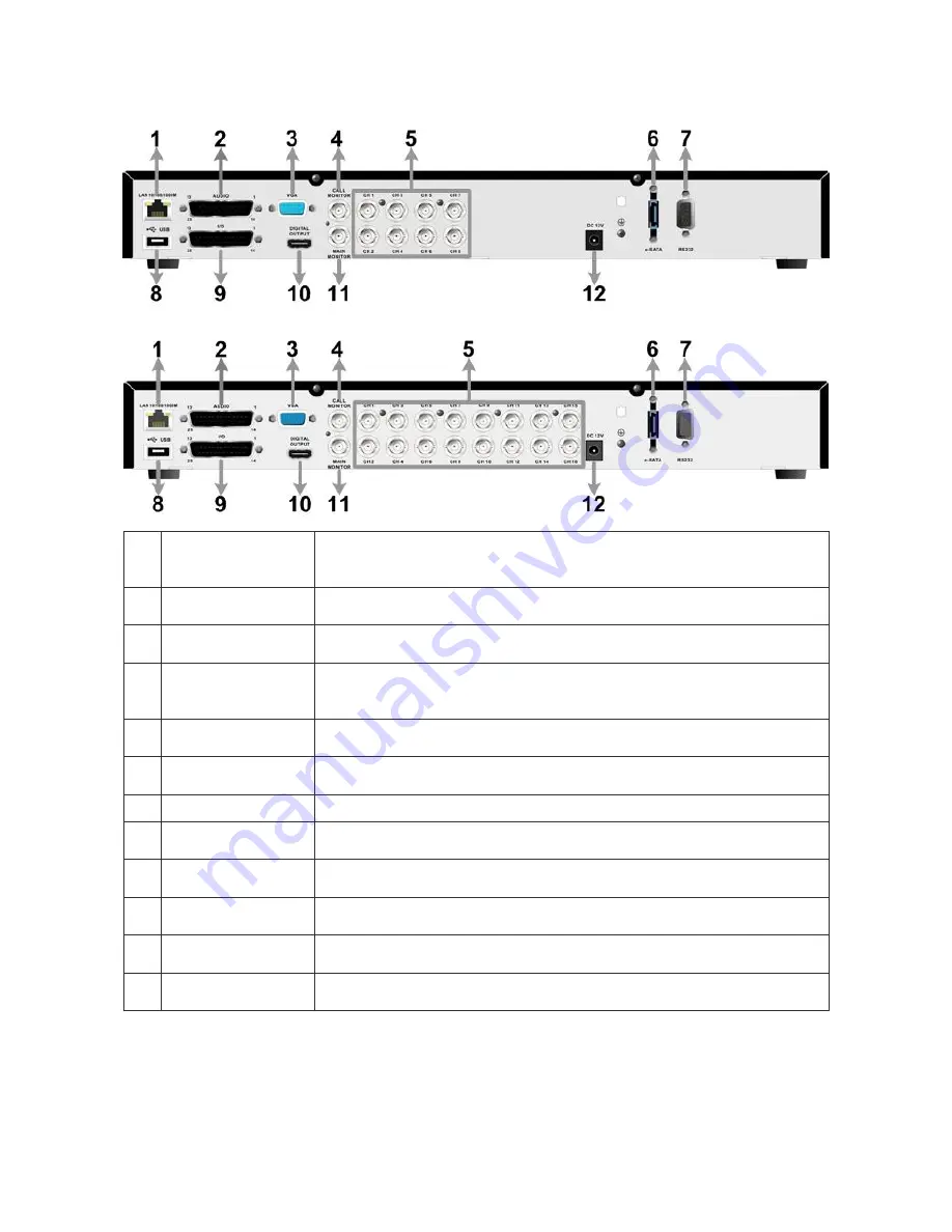
background image

8CH/16CH models: 


LAN 10/100/1000M 
(RJ-45) 

The DVR is capable of networking. Once the unit is connected to the 
LAN network, users can remotely access the DVR through the remote 
software on a PC. 

Audio 

A  D-Sub  Audio  connector  is  provided  for  the  DVR  to  connect  audio 
source devices and Main/Call monitors audio ouput devices.   

Main Monitor 

– 

VGA   

The DVR can connect a VGA monitor via the VGA connector.   

Call Monitor 
(BNC) 

The  call  monitor  is  used  to  display  full  screen  video  of  all  installed 
cameras in sequence. The BNC Call Monitor connector allows users 
to connect the DVR with an optional call monitor.   

Video In   
(BNC) 

A group  of  BNC  connectors  is  provided for  video  input  streams from 
installed cameras. 

e-SATA 

Users can connect an e-SATA storage device via this port to expend 
HDD capacity of the DVR. 

RS232 

The RS232 communication port is for connection to a POS device. 

USB Port 

This  USB  port  allows  users  to  connect  a  USB  mouse  with  PS/2 
protocol. 

Alarm I/O & 
RS-485 

The  DVR  provides  alarm  I/O  and  RS485  ports  that  offer  users  the 
flexibility required to connect the DVR to other devices. 

10 

Main Monitor 

– 

Digital Output 

The  DVR  can  connect  to  a  Digital  Output  monitor  via  an  optional 
Digital Output connector.   

11 

Main Monitor- 
BNC 

The DVR can connect to a monitor via a BNC connector.   

12  Power Jack 

The  DVR  has  a  12V  DC  power  connection  jack. Please  connect  the 
power supply adapter shipped with the unit.   


Summary of Contents for EDNS V1000

Page 1: ...screen 2 In input interface 1 10 can be used for direct input of numbers 0 9 3 In Dome Camera Control mode 1 is for entering the Set Go preset menu 11 16 is for quick access of preset points 1 6 8 Power LED It lights up when power source is connected 9 Alarm LED It lights up when an alarm is triggered 10 Network LED It lights up when network is connected In addition it blinks when data is being tr...

Page 2: ...connect the DVR with a call monitor 5 Video In BNC A group of BNC connectors is provided for video input streams from installed cameras The DVR will detect video source of CH1 and automatically adjust the system to NTSC or PAL video system 6 e SATA Users can connect an e SATA storage device via this port to expend HDD capacity of the DVR 7 RS232 The RS232 communication port is for connection to a ...

Page 3: ...5 Video In BNC A group of BNC connectors is provided for video input streams from installed cameras 6 e SATA Users can connect an e SATA storage device via this port to expend HDD capacity of the DVR 7 RS232 The RS232 communication port is for connection to a POS device 8 USB Port This USB port allows users to connect a USB mouse with PS 2 protocol 9 Alarm I O RS 485 The DVR provides alarm I O and...

Page 4: ...14 16CH only 3 Audio 5 12 Call Audio 21 Audio 16 16CH only 4 Audio 7 13 Main Audio 22 GND 5 Audio 9 16CH only 14 Audio 2 23 GND 6 Audio 11 16CH only 15 Audio 4 24 GND 7 Audio 13 16CH only 16 Audio 6 25 Reserved 8 Audio 15 16CH only 17 Audio 8 9 GND 18 Audio 10 16CH only Alarm I O RS 485 Pin Definition Pin Definition Pin Definition 1 Alarm Out Open 10 Alarm In 5 19 Alarm In 10 16CH only 2 Alarm Out...

Page 5: ...ia either the DVR or DVRRemote the remote software Enter OSD Main Menu Press MENU to enter the OSD main menu Select the administrator account admin to login Enter the preset password 1234 It is strongly suggested to change the password to prevent unauthorized access Date Time Setting Follow steps below to setup date time before the recording starts Refer to the User s Manual for advanced setup of ...

Page 6: ... information from the network service provider To change the IP address Netmask Gateway and DNS value press UP DOWN keys to move the cursor to the item Use LEFT RIGHT keys to access each section of the value and press ENTER then change the value using UP DOWN keys PPPoE users must set the PPPoE Account PPPoE Password and PPPoE Max Idle as well When the settings are complete press ENTER to confirm ...

Page 7: ...er must match the ID address defined by the dome camera To configure the RS 485 parameters select System Setup from OSD main menu and then select RS485 Setup The default RS 485 settings are 9600 Baud 8 Data Bits 1 Stop Bit and No Parity Control Buttons in Dome Camera Control Mode 1 Iris Open 5 Zoom Out 9 Enter Dome Camera Control Mode 2 Iris Close 6 Zoom In 10 Pan Tilt 3 Focus Far 7 Set Go Preset ...

Page 8: ... select a channel Move the cursor to Event List and press ENTER to list the event video of the selected channels The list displays each event by date time triggered camera and alarm type The latest recorded event video will be listed on the top To exit the event list press ESC Use UP DOWN keys to scroll through the Event List Press ENTER to play back the selected event record NOTE The event list d...

Page 9: ...onitor 15 Stamp A 3 Monitor Active Inactive 16 Stamp B 4 Sequence 17 Lock 5 Record 18 Disk Error 6 Event Record 19 Disk Full 7 Freeze Live Mode 20 Disk Overheat 8 Dome Camera Control 21 No Disk 9 Zoom 22 Disk Almost Full 10 Forward Playback Speed 1x 2x 4x 8x 16x 32x 23 HDD Usage 11 Pause Playback mode 24 Guest 12 Backward Playback Speed 1x 2x 4x 8x 16x 32x 25 User s Authority Level 13 End of Video...

Page 10: ...OK to accept the settings and close the Security Settings screen Using the Remote Software Start the IE and enter the IP address of the Versatile H 264 DVR in the address bar The ActiveX controls and plug ins dialog will show twice for confirmation click YES to accept ActiveX plug ins The DVRRemote plug ins will be downloaded and installed on the PC automatically when the connection is successfull...

Page 11: ...ecording 10 Search Event List 2 Deflicker On Off at Playback 11 Capture Snapshot 3 Smoothen the Image 12 4 3 Viewing Aspect 4 Audio On Off 13 HDD Status 5 Select Camera 14 Playback Control 6 Display Mode 15 Select Picture Size 7 View Live Camera 16 Bandwidth Normal Dual Stream 8 Playback Video 17 Download DVRPlayer 9 Setup Menu For more information on DVRRemote see User s Manual ...

Page 12: ...Open and the file selection screen is displayed Select the drv video file to playback and click OK Click OK to start the playback or click Cancel to abort View the video playback using the Playback controls To end the playback click Live to return to live video Playback Local avi Files Start the windows media player or other media player from Start menu or any other possible access Select File and...

Reviews: