Use and maintenance manual
Press device
Model: FRA-100
___________________________________________________________________________________________________________________________________________________________
P a g 1 5
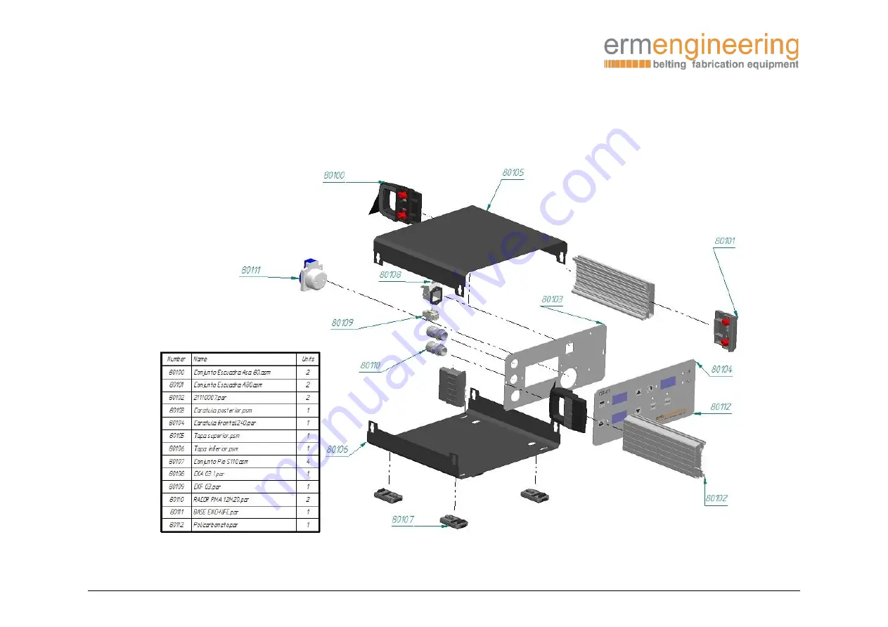
-
Spare parts
Page 1: ...nd maintenance manual Type Press device Model FRA 100 IMPORTANT Read this user manual and follow the instructions and warnings before operating this device Any modification or transformation performed on this machine may cause loss of the manufacturer s guarantee and liability This manual must always remain near to the machine and visible to all the operating and maintenance staff for any future c...
Page 2: ...____________________________________________________________ P a g 2 Index Page CE Declaration of conformity 3 Description of the equipment 4 Technical characteristics 4 Workshop installation 4 Instructions for use 6 Preparing the joint 7 Inflation 9 Programming 9 Electrical drawings 13 Spare parts 15 ...
Page 3: ...d by the directives of the Official Journal of the European Communities 2006 42 CE Machinery Directive 2014 35 UE Low Voltage Directive 2014 30 UE Electromagnetic Compatibility Directive Complies with the design and construction specifications of the European Standards on General Machine Safety EN 349 EN 614 1 EN 614 2 EN 12100 EN 11161 1 EN 1005 1 EN 1005 2 EN 1005 3 EN 1005 4 EN 13849 1 EN 13849...
Page 4: ...ooling circuit by water and by air in some models too Technical characteristics Model FRA 100 Control box unit options CB02 CB01 3 Dimensions LxWxH 1630x800x1570mm Weight 340kg Maximum temperature 200ºC Minimum length belt mm 1250 Heating area mm 1050x160 Maximum pressure 2 5 bar Heating time 20ºC 170ºC 6 min Cooling time with water 25ºC 170ºC 50ºC 1 7min Voltage V 3x230 3x400 Power W 4080 Worksho...
Page 5: ...ace the control board on the rack at eye level safely to avoid it breaking or falling Level the support with the regulation screws located inside the three legs NOTE Once the frame is leveled you most to introduce the trolley to level the wheels The distance between bottom plate and steel plate of trolley is 1 or 2 mm We can modify this distance across the wheel s screws ...
Page 6: ...e line installation of a one way valve at each press is recommended thus avoiding water entering the other presses during the purge process Connect control board CB 01 For further information consult the User Manual for CB 01 Instructions for use Open the press by releasing and extracting the two closing bolts located at both ends of the top plate WARNING Before opening the press check that the in...
Page 7: ...nd the same material offered up to weld at both ends and properly tangential to the belt and fix them using the same holding bar It is also possible to use metal callipers of the same thickness as the belt and when necessary use scraps of the same belt after the callipers to fill out the welding zone NOTE It is always recommendable to fill out the material at least to 70 of the pressing surface to...
Page 8: ...on completing the welding we guarantee that the joint zone has the same texture and finish as the rest of the belt Before closing the press we place the metal or fibreglass plate according to the material to be welded to avoid marks caused by the radical change of temperature and pressure outside the welding zone We introduce the trolley inside the press and down the top plate Once the upper plate...
Page 9: ...lanced way We can now proceed to inflate Inflation WARNING Always make sure the press is correctly closed before inflating There is a risk of explosion of the top plate We inflate the press turning the white wheel of pressure control until bar required We control the inflation visually using the manometer Programming At the moment of starting up the board the actual temperatures of both plates are...
Page 10: ...ese values we must hold down the button for 3 seconds and change the value using the central keys The board shall memorise these values showing the present ones again NOTE The minimum and maximum temperatures that may be programmed are 30 to 200 ºC We shall perform the same operation to program the welding time ALWAYS IN MINUTES The values shown are complete minutes without decimals ...
Page 11: ...value except for starting the count that shall show the count down until ending Once the temperatures and time values are programmed we press START NOTE To halt the process or to make any change after beginning with START we must press STOP and the cycle will stop When the welding time ends the relevant orange LED to start that operation shall turn on When the STOP led shows on the board it means ...
Page 12: ..._________________________________________________ P a g 1 2 If we have the CU 01 cooling control unit the cooling and purging operations shall be performed automatically Once the welding has ended we deflate the press pressure reducing the pressure until 0 bar We can then proceed to open it and up the top plate ...
Page 13: ...l Press device Model FRA 100 ___________________________________________________________________________________________________________________________________________________________ P a g 1 3 Electrical drawings 3 Ph x 400 V ...
Page 14: ...aintenance manual Press device Model FRA 100 ___________________________________________________________________________________________________________________________________________________________ P a g 1 4 ...
Page 15: ...ance manual Press device Model FRA 100 ___________________________________________________________________________________________________________________________________________________________ P a g 1 5 Spare parts ...
Page 16: ...aintenance manual Press device Model FRA 100 ___________________________________________________________________________________________________________________________________________________________ P a g 1 6 ...
Page 17: ...aintenance manual Press device Model FRA 100 ___________________________________________________________________________________________________________________________________________________________ P a g 1 7 ...
Page 18: ...aintenance manual Press device Model FRA 100 ___________________________________________________________________________________________________________________________________________________________ P a g 1 8 ...
Page 19: ...aintenance manual Press device Model FRA 100 ___________________________________________________________________________________________________________________________________________________________ P a g 1 9 ...
Page 20: ...aintenance manual Press device Model FRA 100 ___________________________________________________________________________________________________________________________________________________________ P a g 2 0 ...
Page 21: ...aintenance manual Press device Model FRA 100 ___________________________________________________________________________________________________________________________________________________________ P a g 2 1 ...